
Impedance is the resistance of a circuit or device to current, and the output impedance is the impedance measured at the exit. The lower the impedance, the higher the ability to drive a larger load.
Outputimpedance The internal impedance of the equivalent voltage source (the Thevenin equivalent circuit) or the equivalent current source (Norton equivalent circuit) of the independent power network output port. Its value is equal to the input impedance seen from the output port when the independent power supply is set to zero.
Output impedanceCorresponding to the input impedance is the output impedance.
The output impedance refers to the equivalent impedance of the circuit when the circuit load is viewed from the output port of the circuit. In fact, it is mainly for the energy source or the output circuit. It is the impedance measured by the energy source at the output. Resistance.
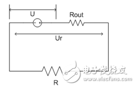
Voltage source driven circuitWhen the voltage source is applied to the load, in addition to consuming energy at the load end, it also generates energy consumption. Here, because the voltage source outputs energy, there is an internal impedance that hinders the energy output, such as the internal resistance of the battery. For example, constant voltage source U, output impedance is Rout, load terminal voltage is Ur, load R, current is I=U/(Rout+R), load terminal voltage Ur=I*R=U*R/(Rout+R) The power generated by the load is P=Ur*I=U2*R/(Rout+R)2. From this formula, the smaller the output impedance, the greater the ability to drive the load.
Current source driven circuit
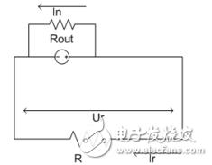
For a circuit driven by a current source, there is also an output impedance, and the output impedance is connected in parallel across the constant current source.
The current source outputs a constant current I, a part of In consumes the internal resistance Rout, and the remaining current Ir is consumed on the load R. It can be seen that the voltage on the load R is Ur=Ir*R, and the voltage across the internal resistance Rout is the same. That is, Ur=Ir*R=In*Rout, and because I=Ir+In is derived, Ur=I*Rout*R/(Rout+R), load power:
P=Ur*Ir=Ur2/Rout=I2*Rout*R2/(Rout+R)2=I2*R2/(Rout+R2/Rout+2R)
From this, it can be seen that when Rout=R, the external end load P is the largest. Therefore, for a constant current source load, in order to obtain the maximum power, it is necessary to match the resistance value of the load with the internal resistance of the current source, that is, to approach the same value as much as possible.
Load capacity is the amount of output current that represents the device. For standard TTL devices, the output load capability is 0.4mA high, while the TTL device as a lower-level load has an input high-level current of 0.04mA (40uA), so a standard TTL device can drive up to 8 standard TTL loads. .
Load capacity refers to the ability of the output voltage or current to be unaffected by an external device. For example, if a microcontroller's pin outputs a 5 volt signal, if it is connected to a load and its 5 volts remain unchanged, then it can drive the load. If it is smaller, it means that the load is not loaded. Similarly, if the output current can meet the load requirements, then the load capacity meets the requirements and vice versa.
Output impedance vs. load capacityThe output impedance is the internal resistance of a signal source.
For an ideal voltage source (including the power supply), the internal resistance should be zero, or the impedance of the ideal current source should be infinite.
In reality, the voltage source cannot do this. We use an ideal voltage source in series with a resistor r to be equivalent to an actual voltage source. This resistor r in series with the ideal voltage source is the internal resistance of the (source/amplifier output/power supply). When this voltage source supplies power to the load, current I flows through the load and produces a voltage drop of I x r across this resistor. This will cause a drop in the output voltage of the power supply, which limits the maximum output power.
Similarly, for an ideal current source, the output impedance should be infinite, but the actual circuit is not possible. The current source is actually equivalent to an ideal current source in parallel with a resistor. This resistor is the output impedance R. The larger the R is, the closer it is to the open circuit, and the smaller the influence on the latter circuit, because the resistance of the latter circuit is parallel. Still it.
For the load capacity, it can be understood as the output power. Specifically, the analogy: the stronger the load capacity, the original can drive a bicycle, and now can drive a car forward. The load can be a bulb, a speaker, a motor, etc.
According to the principle of resistance voltage division, the voltage division in the series circuit is proportional to the resistance value. The larger the resistance value is, the more the voltage is divided. Therefore, the smaller the output resistance of the voltage amplification circuit, the less it is under the same power consumption condition. The load with the same impedance is the lower the voltage that is divided and consumed on itself, and the higher the voltage on the load, so the amplifier with lower output resistance can bring more power than the amplifier with high output resistance. The internal resistance is smaller and the load comes.
The connection between "greater power" and "smaller internal resistance" means that under the same conditions, if the power of the tubes is different, there is no comparability.
The power of the load is related to the supply voltage and the output current of the final stage drive tube, but if the internal resistance of the selected tube is small, the electric energy can be sent to the load as much as possible instead of being consumed on the power tube. In this way, when there is the same amount of power input, it can be mentioned that "more power" is actually higher efficiency.
A typical high power amplifier uses a MOSFET tube because its internal resistance is smaller.
In general, the output impedance of the voltage source is as small as possible, and the output impedance of the current source is as large as possible (Note: only suitable for low-frequency circuits, in high-frequency circuits, impedance matching is also considered. In addition, current limiting is required. Except for signal sources with voltage limiting protection).
FOLI Prefilled Pod Starter Kit
FOLI BOOM PREFILLED POD ECO-FRIENDLY STARTER KIT
☞12ml Eliquid Capacity
☞600mAh Battery
☞Type-C Rechargeable
☞30mg/ml Nicotine Strength
☞6000 Puffs
☞12 Flavors Optional
>FEATURES
-The firstpen -like prefilled pod starter kit you ever have
-Mesh coil for the pure and original taste
- Easy to tell the battery yolume by 7-color of LED indicators.
-12ml prefilled pods replaceable
-Type-Gcharging port design.
- Multiple colors, intense flavor and various experience
12 TOP FLAVORS
Cola Beats
Greer Gape
Peach lce
Margo ce
Kunquat Passion Fruit
Watermelon Ice
Cooll Mint
Lychee lce
Blueberry Raspberry
Strawberry lce Cream
Strawberry Ice
Mung Bean

FOLI Prefilled Pod Starter Kit, ECO-FRIENDLY STARTER KIT, FOLI Disposable Vape Replaceable, Elfbar Prefilled Pod Starter Kit
Tsvape E-cigarette Supplier Wholesale/OEM/ODM , https://www.tsvaping.com