The importance of analog circuits Small partners understand! The most basic is 20 analog circuits, we must understand!
The junior partner is skilled in remembering these twenty circuits and knowing the role of these twenty circuits.
The mid-level partner is able to analyze the role of the key components in these twenty circuits. What happens to the function of the circuit when each component is faulty, how the parameters change during measurement, and how to handle faulty components? Analysis of the circuit signal flow, phase changes; qualitative analysis of signal waveform changes; qualitative understanding of the circuit input and output impedance size, signal and impedance relationship. With these circuit knowledge, you are very likely to grow into an outstanding maintenance technician for electronic products and industrial control equipment. The most interesting thing is that, at this time, you can use it as a freelancer to come and receive packets, use the Internet model and your own ability to make money outside of work, and be happy!
The senior partner is able to quantify the input/output impedance of these twenty circuits, the ratio of the output signal to the input signal, the relationship between the signal current or voltage in the circuit and the circuit parameters, the amplitude and frequency characteristics of the signal in the circuit, phase and frequency Relationship characteristics, selection of components and parameters in the circuit, etc. After reaching the advanced level, as long as you are willing, well-respected high-paying occupations - the development and design engineers of electronic products and industrial control equipment will be your first choice. Of course, as a master of technology, you can often make moves to solve technical problems. I love to help you earn a lot of money together! Think drunk!
A bridge rectifier circuit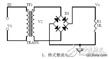
1. Unidirectional Conductivity of Diode: Volt-ampere Characteristic Curve: Ideal Switch Model and Constant Voltage Drop Model:
2, bridge rectifier current flow process: input and output waveforms:
3. Calculation: Vo, Io, diode reverse voltage.
Second, the power filter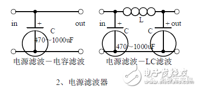
1, the process of power supply filtering analysis: waveform formation process:
2. Calculation: Filter capacitor capacity and pressure value selection.
Third, the signal filter1, the role of the signal filter: the difference and the same point with the power filter:
2. The impedance calculation of LC series and parallel circuits, amplitude-frequency relationship and phase-frequency relationship curve.
3. Draw a passband curve.
Calculate the resonant frequency.
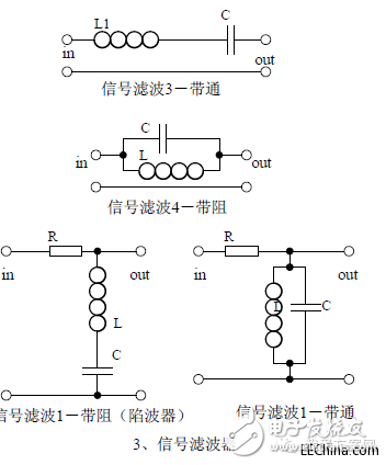
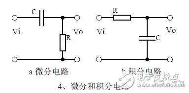
1, the role of the circuit, and the difference between the filter and the same point.
2, differential and integral circuit voltage change process analysis, draw a voltage change waveform diagram.
3. Calculation: Time constant, voltage change equation, selection of resistance and capacitance parameters.
V. Common emitter amplification circuit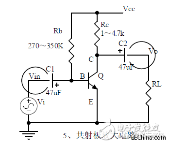
1, triode structure, triode current relationship, characteristic curve, amplification conditions.
2, the role of components, the use of the circuit, voltage amplification, input and output signal voltage phase relationship, AC and DC equivalent circuit diagram.
3, static operating point calculation, voltage amplification calculation.
Six, partial pressure biased common emitter amplifier circuit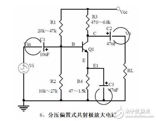
Note points:
1, the role of components, the use of the circuit, voltage amplification, input and output signal voltage phase relationship, AC and DC equivalent circuit diagram.
2. The analysis of current series negative feedback process and the influence of negative feedback on circuit parameters.
3, static operating point calculation, voltage amplification calculation.
4. Controlled source equivalent circuit analysis.
Collective electrode amplifying circuit (emitter follower)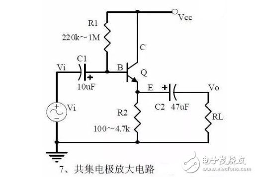
Note points:
1, the role of components, the use of the circuit, voltage amplification, input and output signal voltage phase relationship, AC and DC equivalent circuit diagram. Circuit input and output impedance characteristics.
2. The analysis of current series negative feedback process and the influence of negative feedback on circuit parameters.
3, static operating point calculation, voltage amplification calculation.
Eight, circuit feedback block diagram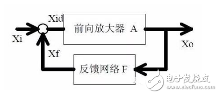
Note points:
1. The concept of feedback, positive and negative feedback and its judgment methods, parallel feedback and series feedback and judgment methods, current feedback and voltage feedback and their judgment methods.
2. Amplification gain with negative feedback circuit.
3, negative feedback on the circuit's amplification gain, passband, gain stability, distortion, input and output resistance.
Nine, diode regulator circuit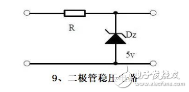
Note points:
1, the characteristics of the voltage regulator diode.
2, Zener diode application considerations.
3, analysis of the voltage regulation process.
Ten, series power supply
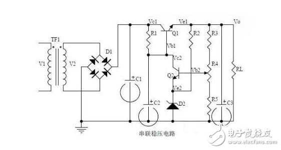
Note points:
1. The block diagram of series regulated power supply.
2, the role of each component; analysis of the regulation process.
3, the output voltage calculation.
Eleven, differential amplifier circuit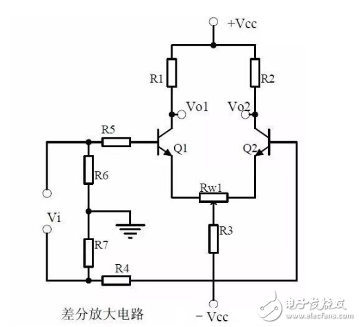
Note points:
1, the role of various components of the circuit, the use of the circuit, the characteristics of the circuit.
2, the working principle of the circuit analysis. How to amplify differential mode signals and suppress common mode signals.
3, the circuit single-ended input and double-ended input, single-ended output and double-ended output mode of operation.
12. Field effect transistor amplification circuit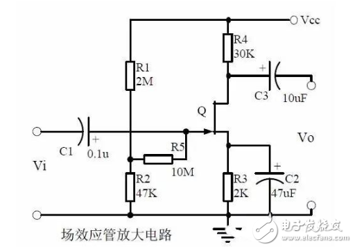
Note points:
1. Classification, characteristics, structure, transfer characteristics and output characteristics of FETs.
2, the characteristics of the field effect amplifier circuit.
3, field effect amplifier circuit applications.
Thirteen, frequency selection (band pass) amplifier circuit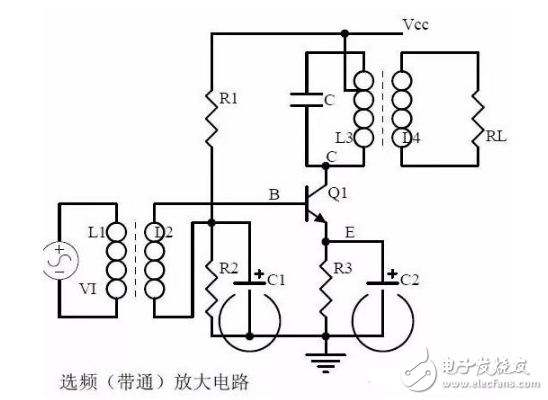
Note points:
1, the role of each component
Selective frequency amplification circuit features
The role of the circuit
2. Calculation of characteristic frequency
Selecting frequency component parameters
3, amplitude frequency characteristic curve
XIV. Operational Amplifier Circuit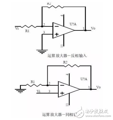
Note points:
1. The concept of an ideal operational amplifier
Virtual short circuit at the input of the op amp
A virtual circuit breaker at the input of the op amp
2, the main purpose of the inverting input mode op amp circuit
The phase relationship between the input voltage and the output voltage signal
3, the gain expression under the same phase input mode
input resistance
Output impedance
Fifteenth, differential input operation amplifier circuit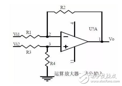
Note points:
1, the characteristics of differential input operation amplifier circuit
use
2. The relationship between output signal voltage and input signal voltage
16. Voltage comparator circuit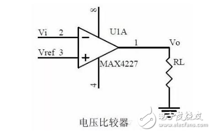
Note points:
1, the role of voltage comparator
work process
2. Comparator input-output characteristic diagram
3, how to constitute a hysteresis comparator
17. RC Oscillator Circuit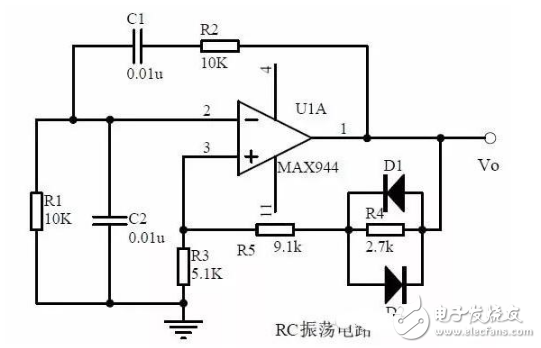
Note points:
1, the composition of the oscillation circuit
The role of oscillation circuit
Oscillation circuit start-up phase condition
Oscillation circuit start-up and balance amplitude conditions
2, RC circuit impedance and frequency curve
Phase vs. frequency curve
3, RC oscillator circuit phase condition analysis
Oscillation frequency
How to choose components
Eighteenth, LC oscillating circuit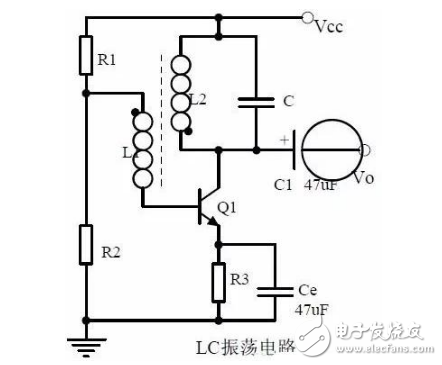
Note points:
1. Analysis of oscillation phase conditions
2, DC equivalent circuit diagram and AC equivalent circuit diagram
3, oscillation frequency calculation
19. Crystal oscillator circuit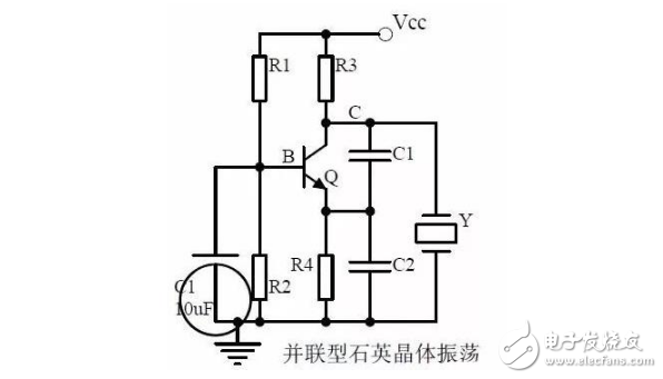
Note points:
1, the characteristics of quartz crystal
Quartz crystal equivalent circuit
Quartz Crystal Characteristics
2, the characteristics of quartz body vibrator
3, quartz crystal oscillator oscillation frequency
Twenty, power amplifier circuit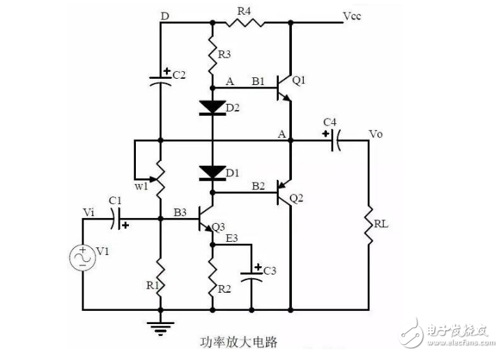
Note points:
1, B class power amplifier work process and crossover distortion;
2. Composite rules of composite triodes;
3, Class A and Class B power amplifier work principle, bootstrap process, Class A power amplifier, Class A and Class B power amplifier features.
How much is your "fever"?
If you are burning at the beginning, then you must be able to remember these twenty circuits and be clear about the effect of these twenty circuits.
If you are medium-fired, then you can analyze the role of the key components in the twenty circuits, what the function of the circuit is affected by each component failure, the change of the parameters when measuring, master the components of the fault The method of processing; You can also qualitatively analyze the flow of the circuit signal, phase changes, qualitative analysis of signal waveform changes, qualitative understanding of the circuit input and output impedance size, and signal and impedance relationship.
If you have been able to quantitatively calculate the input and output impedances of these twenty circuits, the ratio of the output signal to the input signal, the relationship between the signal current or voltage in the circuit and the circuit parameters, the relationship between the amplitude and frequency of the signal in the circuit, and the relationship between phase and frequency Characteristics, selection of components and parameters in the circuit, etc. Congratulations, you are already a high fever 39.5 degree electronic engineer veteran!
Lithium Iron Phosphate Battery
FEATURES & BENEFITS
Saintish 12.8V Lithium Iron Phosphate Battery built-in BMS to protect it from overcharge/discharge, temperature and short circuit. Monitors the battery operation status on mobile devices in real time with the built-in Bluetooth module.
Grade A prismatic battery cells ensure a more than 3000 cycles lifespan, which is more than 10 times to Lead Acid with 200~500 cycles. Wide operating Temp: Charge: 0°C~45°C; Discharge: -20°C~60°C.
The portable lithium battery pack's case material is ABS-FR material and the enclosure protection is IP65 waterproof, which lets you free from worrying about installing batteries indoors or outdoors. LiFePO4 Battery supports series(Up to 4 pcs) and parallel(up to 4pcs) connections.
Lithium Iron Phosphate Battery, 12.8V Lithium Battery, Rechargeble Battery, Lithium Battery for Caravan
Hangzhou Saintish Technology Co.,Ltd. , https://www.saintishtech.com
