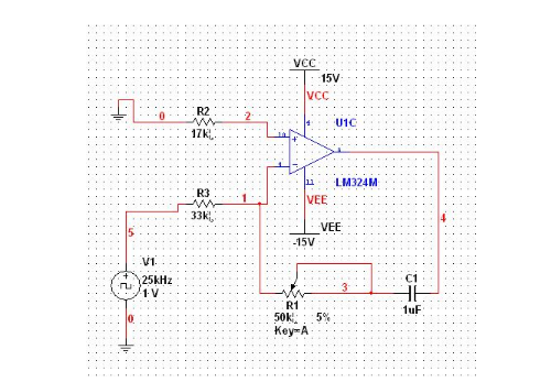
It is a simple integration circuit. The frequency is constant, and the level after integration is equivalent to averaging the area of ​​the high level voltage and the corresponding time to one cycle. Basically the duty cycle is 50%, the converted voltage is 50% of the highest voltage, the duty cycle is 30%, and the analog voltage is 30%. If the PWM is 5V level, the converted DC voltage is 2.5V and 1.5V.
Integral Circuit Usage Integral circuits are commonly used in scanning circuits for black and white and color televisions.
The structure of the integration circuit The structure of the integration circuit is similar to that of the resistor divider circuit, and is more similar to the differential circuit except that the resistance and capacitance in the differential circuit are swapped. This is another voltage divider circuit that consists of a capacitor and a resistor. However, the input of the integrating circuit is not a sinusoidal signal, but a pulse signal, which is also the difference between the integrating circuit and other voltage dividing circuits.
Integral circuit requirements In the integration circuit, the RC time constant (resistance value multiplied by the capacitance value) is required to be much larger than the pulse width. This is the requirement that the resistance and capacitance must be satisfied in the integration circuit. This is the differential circuit and the integration circuit. A difference.
The function of the integration circuit The integration circuit and the differential circuit also perform inversely in terms of function: the average value of the input signal can be extracted, that is, the low frequency component. The circuit function is somewhat similar to the capacitor filter circuit. High-frequency components are extracted from the circuit to fill the low-frequency components, so as to achieve an average change in the circuit frequency.
The principle of the integration circuit The integration circuit and the differential circuit are only the resistance and capacitance exchange positions in the structure, and the integration circuit diagram can be imagined from the differential circuit diagram. In the integration circuit, the circuit input rectangular pulse signal U1 is applied to the resistor, and after the resistor, the triangular pulse signal U2 is outputted on the capacitor. This circuit can also be understood as follows: input a rectangular pulse signal on the resistor and capacitor series circuit, use the oscilloscope to view the circuit waveform, there will be a rectangular pulse signal in front of the resistor, and a triangular pulse signal in front of the capacitor. This mainly utilizes the characteristics of capacitor energy storage and charging to convert the rectangular pulse signal in the circuit into a triangular pulse signal and deliver it to the next stage circuit. The triangular pulse wave is relatively stable compared to the rectangular pulse wave. The rectangular wave is obviously falling together. Although the triangular wave has fluctuations, the fluctuation is not as fast as the rectangle. It seems that the integration circuit is almost the same as the filter capacitor.

The analysis process of the integral circuit principle should be carried out according to the input pulse signal in the frontier stage, the flat top stage and the trailing edge stage:
1. When the rectangular pulse of the input signal has not appeared, the input signal voltage is zero, so the output signal voltage is also zero.
2. When the rectangular pulse of the input signal appears, the input signal charges the capacitor through the resistor. Since there is no charge at the beginning of the capacitor, the capacitor will be short-circuited, that is, the voltage that the capacitor is subjected to at the beginning is zero, and the output signal voltage is also zero.
3. When the rectangular pulse of the input signal appears, as the charge of the capacitor increases continuously, the voltage withstand by the capacitor also increases, and the output signal voltage also increases. The current flowing through the capacitor is approximately proportional to the magnitude of the input pulse signal voltage, so the magnitude of the output signal voltage is approximately proportional to the integral of the input signal voltage, and the integrating circuit is thus named.
4. When the rectangular pulse of the input signal disappears, the voltage of the resistor will suddenly change to zero, and the capacitor will discharge the resistor. The voltage of the output circuit is the discharge voltage of the capacitor. As the discharge progresses, the voltage of the capacitor becomes lower and lower, and the voltage of the output circuit becomes lower and lower.
5. When the rectangular pulse of the input signal disappears, since the time constant required by the integration circuit is much larger than the pulse width, the discharge speed is relatively slow, and the next pulse signal comes again when the capacitor has not been discharged. Since the capacitor is just discharged and the voltage is lower than the input signal voltage, the capacitor starts to charge again. As the voltage of the capacitor is increased, the output voltage becomes larger. Repeatedly, one pulse circulates again and again.
RandM Squid Box is a disposable vape device with cool design and it is rechargable. It contains 12ml 0/2/3/5% nicotine salt e-juice and vape up to 5200 puffs. There are 20 flavors for you to choose. The rechargeable Type-C port at the buttom of the device gurantting you finish the last drop of the ejuice in the tank all the time.
RandM Squid Box Disposable Device Features:
☑0/2/3/5% Nicotine Salt.
☑12ML of E-liquid.
☑Mesh Coil
☑Battery Rechargable
☑Integrated 850mAh Battery.
☑20 Flavors Available.
☑10pcs in a display box.
☑240pcs in a carton.
Flavors Available:
1.Strawberry Kiwi
2.Blueberry Ice
3.Lush Ice
4.Cotton Candy
5.Mixed Berries
6.Banana Ice
7.Strawberry Lychee
8.Mint
9.Aloe Grape
10.Peach Mango

Randm Squid Box,850Mah Rechargeable Vapes ,E Cigarettes Vapes ,Disposable Vape Pen Stick
Shenzhen Kester Technology Co., Ltd , https://www.kesterpuff.com
