
Central issue:
This article refers to the address: http://
- Traditional diode protection method for reverse polarity of automotive electronic equipment
- Polymer positive temperature coefficient protection method for reverse polarity of automotive electronic equipment
solution:
- Protection of high power MOSFET circuits
- Motor protection
Automotive electronics must have protection against power supply polarity reversal. When the jumper cable is connected to the wrong polarity terminal, or when it is connected to an overdischarged battery, and when the new battery is installed upside down, the power polarity is reversed. If no corresponding protective measures are taken, excessive heat is applied. This can cause malfunction of the electronic module or cause damage to load devices such as solenoid valves and motors on the vehicle, resulting in unsafe hazards. Traditional protection techniques are expensive and can cause excessive voltage drops that affect the performance of certain systems. New technologies using polymer positive temperature coefficient (PPTC) devices, such as Raychem's PolySwitch products, can address these shortcomings simultaneously, with other advantages.
Traditional diode protection
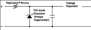
In order to protect the electronic module from damage due to reverse polarity of the battery, a common solution is to use a forward-conducting (rectifying) diode to prevent reverse current flow (see Figure 1).

The most fundamental disadvantage of using forward conduction diodes is the inherent voltage loss (0.7 to 1.0 V) and the actual supply voltage of the electronic module. For some automotive electronic modules in the system (such as engine controls), the operating voltage is critical and any form of voltage drop (such as the voltage across the forward-pass diode) is reduced to ensure that the vehicle is at battery voltage. Normal starting at a lower state is of great significance. In other cases, such as audio systems, the system voltage has a direct impact on the output power (Po = V * I = V2 / R). In other words, it will directly affect the audio performance. In order to minimize voltage loss, some electronic modules use Schottky diodes to reduce the voltage drop. In general, the voltage drop can be controlled below 0.5V.
If a standard rectifier diode or Schottky diode is used in the protection of the polarity of the battery, the current carrying capacity (current rating) of the diode depends on the size of the load to be connected to the diode. The standard rectified forward conduction diodes are relatively low cost (less than $0.05) when the current through the electronic module is less than 1A. However, if a Schottky diode is used, or if the current exceeds 1A, the cost will increase relatively.
Another factor to consider when choosing the size of a forward conducting diode is the amount of inrush current and the ability of the device to absorb and dissipate the inrush current that occurs during "load interruption." When the alternator is supplying current, disconnecting the battery of the car will cause an event of load interruption. In general, this load-breaking waveform will reach its peak voltage within a few milliseconds. For silicon devices, it is often necessary to take into account the worst-case rating.
Polymer positive temperature coefficient protection
For example, a polymer positive temperature coefficient device such as a PolySwitch product consists of a composite of a semi-crystalline polymer and conductive particles. Under normal operating conditions, the conductive particles within the device form a low resistance path that allows current to flow. In the event of a faulty condition that causes excessive temperature, such as an overcurrent or an ambient temperature, the crystals in the polymer begin to melt and form an amorphous material, causing separation between the conductive particles, resulting in device A very large non-linear increase in resistance values ​​occurs. This increase in resistance is typically above three orders of magnitude, thereby reducing the current to a relatively low and safe level. The PolySwitch polymer positive temperature coefficient device is reset after the fault is cleared and after the circuit power is disconnected.
The use of PolySwitch devices to replace the forward conduction diodes in the above applications (see Figure 2) offers several advantages including reduced voltage drop because the voltage drop across the polymer positive temperature coefficient (PPTC) device is typically 0.1V. the above. Second, polymer positive temperature coefficient (PPTC) devices provide additional protection (heat traces, wires, relays, solid state components, etc.) for other types of electronic components.
Protection of high power MOSFET circuits
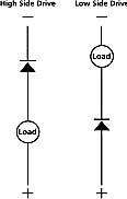
For electronic modules that use high-power MOSFETs for solid-state switching of various loads, other polarity reversals are concentrated on the high-side or low-voltage side of the drive configuration (see Figure 3a). In the reverse polarity state, the intrinsic diode of the high power MOSFET becomes forward biased and allows current to flow to the motor, lamp or solenoid load connected to it (see Figure 3b).
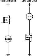
This does not create a state of failure that is instantaneously disrupted. However, the power consumption of the FET will typically increase by a factor of about 5, since the voltage drop across the device is about 1V in this case (current flows through the PN junction of the intrinsic diode) rather than the nominal forward of 0.2V. VDS voltage (measured from the MOSFET to the source). Unless the correct thermal control convention is used, such as using a heat sink of sufficient size to dissipate the heat generated during the polarity reversal state, continuous operation will burn the MOSFET in this case.
This additional heat sink will add to the cost, weight and size of this application, which is where automakers and suppliers want to reduce. Even with thermal protection field effect transistors, such as TEMPFETs, it is not possible to prevent burnout under these conditions because the gate of the FET cannot control the current flowing through the internal diode.
Adding a polymer positive temperature coefficient device in series with the load and coupling it to the bypass diode (see Figure 4d) provides protection against battery polarity reversal and allows for a smaller heat sink. More importantly, it prevents reverse flow of current, thus avoiding abnormal movements of the solenoid valve or motor.
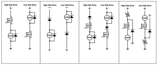
Inductive load and battery polarity reverse
For inductive loads, the most common approach is to use a freewheeling diode connected across the load to suppress voltage spikes that occur when the load is switched off. Figure 4a shows a high power MOS field effect transistor with inductive load for use as a high side and low side switch. In the reverse polarity state, current will flow through the forward biased inner diode in the FET and the freewheeling diode connected in parallel across the load, establishing a direct connection between the positive and negative terminals of the power supply. Short circuit path (Figure 4b). One way to stop this current flow is to use a forward conducting diode as shown in Figure 4c. However, for high current loads, as mentioned earlier, this solution may not be available due to the high cost. Another alternative is to use a polymer positive temperature coefficient device that is coupled to a smaller rectifier diode so that it only needs to withstand the inrush current required to "break" the polymer's positive temperature coefficient device, which must be continuous The forward conduction diodes that support full load current are different.
Motor protection
Most of the low-power motors that make passengers more comfortable and convenient are brush-type DC motors. Two-way motors (such as power windows, power seats and power locks) are driven in an "H-bridge" configuration with four high-power MOS field-effect transistors connected as shown in Figure 5a.
When the motor is rotated in the forward direction, the field effect transistors 1 and 4 are simultaneously turned on; and when the motor is rotated in the reverse direction, the field effect transistors 2 and 3 are simultaneously turned on. In the case of a reverse polarity connection, the equivalent circuit generated for the H-bridge circuit is that two series-in-line diodes are connected in parallel between the positive and negative terminals of the power supply (see Figure 5b), so a short-circuit path is actually established.
For the same reasons described above, it may not be economically feasible to use a series of forward conducting diodes. However, by using a series of polymer positive temperature coefficient devices, it helps to provide an economically viable polarity reversal protection while minimizing voltage losses within the system (see Figure 5c). The equivalent circuit under the polarity reversal condition is shown in Figure 5d. In general, the intrinsic diode of the FET facilitates the provision of a temporary surge current required to break the polymer positive temperature coefficient device within milliseconds.
As shown in Figures 2, 3b, 4d, and 5d, the diode that establishes the current path in the polarity reversal state must have a certain surge capacity rating to cause PPTC in the safe operating area (SOA) of the diode. The device is broken. In other words, the "breaking time" of the polymer's positive temperature coefficient device must never exceed the time limit of the diode's inrush current. Polymer PTC devices are available in a range of current and maximum break time ratings to meet the needs of most applications.
Reduce the power loss of the car
As car loads continue to increase, automakers and their electronics system suppliers are planning the next generation of automotive power systems to replace the 12V battery systems that have been used in automobiles since the 1950s. This PowerNet technology stipulates that the voltage limit of a car's power supply is three times that of a conventional system.
This 42V system includes more stringent specifications for 12V products that are still available for dual voltage construction. As a result, current lower power products can continue to be used for many years and combined with higher power products for common use on the 42V bus. As costs are tied to the evolution to 42V power, automakers are trying to delay the process and look for any opportunities to reduce power consumption.
One way to reduce power consumption is to replace brushed motors with brushless DC currents, especially for higher power applications. Brushless DC motors have the advantage of not wearing out, and because there are no brushes that are prone to arcing, electromagnetic interference is reduced. In a three-phase brushless motor, the topology of the FET bridge is three branches, similar to the two branches of a brushed DC motor. Battery polarity is the same as against brushless DC motors, but fortunately, the polymer positive temperature coefficient device battery reverse protection configuration suggested in Figure 5c can also be used in brushless DC motors.
The use of polymer PTC devices in place of series diodes provides additional benefits for models that are already close to the full capabilities of the available power system. Since the power loss of the series diode is proportional to the voltage, reducing the diode voltage of 0.7V to approximately 0.1V in a 20A circuit can reduce (0.7-0.1) x 20 = 12W. In the number of motors used in general vehicles, this technology can save more than 100W in general.
These three savings methods have the potential to delay the transition to higher voltage systems by one to two years. Some models, such as the GM GMC Sierra and Chevrolet Silverado, will use a limited 42V system in the 2004 model. In the technical specifications for the 42V car, the reverse of the battery is not allowed. These discussed methods can help automakers ensure that these specifications are met.
Fiber Optic Cabinet,Fiber Cabinet,Fiber Distribution Cabinet,Outdoor Fiber Cabinet
Cixi Dani Plastic Products Co.,Ltd , https://www.cxdnplastic.com