This article uses a practical test case to illustrate the difference between measuring power supply ripple and measuring power supply noise in oscilloscope bandwidth requirements and measurement results caused by different bandwidths. The article gives hard conclusions and measurement results.
project descriptionMany problems with hardware circuits are related to power supplies. Good power supply design is critical to the entire hardware circuit; this article is a practical case to talk about how to use the oscilloscope to accurately measure the noise of the power supply.
The measurement object is an IPAD expansion peripheral purchased on the market. This device implements the expansion of the IPAD by installing a corresponding APP on the IPAD and adding a peripheral module to the charging port.
The storage medium used in this device is a MicroSD card. We detect the signal in the storage part of the MicroSD card and check whether this part of the circuit complies with the SD specification. When using an oscilloscope to detect the SDVCC voltage, based on the experience of measuring the power supply ripple, measuring the power supply ripple should generally limit the 20 MHz bandwidth. However, using the 20 MHz bandwidth limit differs greatly from the value measured at full bandwidth of 500 MHz. So, if you measure the voltage of SDVCC here, should you limit the bandwidth to 20MHZ?
problem solvedThis circuit is very simple, which is to expand the product through the power supply port of the IPAD and the data transmission line; firstly, measure the voltage waveform of the product to the SD power supply. According to the range of power supply requirements of the memory chip MicroSD card: 2.7V-3.6V; it is not allowed to exceed this range. Otherwise, the chip will have a relatively large risk when operating under unstable voltage, and even affect the normal operation of the card.
The first thing to consider is the oscilloscope settings. Is there a bandwidth limit of 20 MHz? The detailed usage environment is shown below:
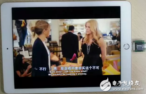
The port that IPAD just brought out can be used as the source of the power supply. When the peripheral module of the back end is tested at the end, the power supply passes through a PCB trace, including some chip loops. There should be high frequency noise. The bandwidth limitation of 20MHZ actually filters out the noise originally belonging to the module. For this reason, we conducted a comparison test to verify:
In the first step, I first verify the output of the IPAD's power supply at work, as shown below:
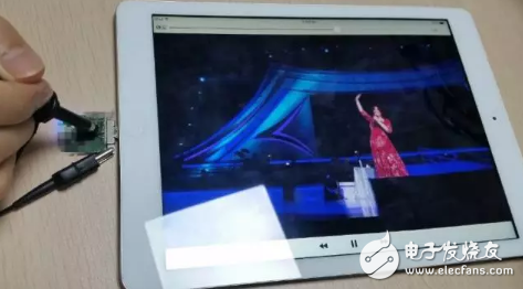
By directly verifying the voltage at the output of the IPAD, the power supply at the source is guaranteed to be normal. Through testing, we found that the voltage measured at the source is around 3.4V (500MHz bandwidth measurement), peak-to-peak maximum 29mV, and is a very stable power supply. ;
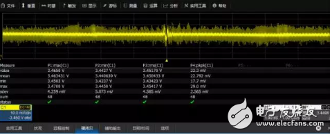
Therefore, the problem of power supply at the source can be eliminated. Next, we measure the voltage directly on the power supply pin SDVCC of the MicroSD card after passing the entire module, as shown below:
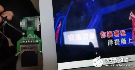
When we tested at the point on the picture, we found that there was considerable noise on the high-frequency switching power supply, which made the voltage exceed the specification requirements, the maximum value reached 3.814V, and the peak-to-peak value was up to 854mV.
But when we set the oscilloscope to 20MHz bandwidth, the high-frequency switching power supply becomes very good, completely within the scope of the power supply requirements;
As described at the beginning of this article, in this high-frequency switching power supply test process, it is not the high-frequency switching power supply ripple measurement, but should be noise. Measurements of such high-frequency switching power supply voltages, such as testing at a bandwidth of 20 MHz, can cause misjudgment in measurement analysis (because there is a large noise/voltage fluctuation), the front-end filtering of the oscilloscope will exist in the product itself. The noise is filtered out; therefore, we tested with a full bandwidth of 500 MHz;
However, does the above test method truly reflect the noise level of the product? In addition, how much deviation will be caused by the test using the standard passive probe? Is it within an acceptable range? Further verification is required;
We used different ground loops to measure the same test points. The spring-loaded test loop reduces the return path of the signal, and the test results are better than the original 6-inch standard, but the difference between the two is small, and the measured maximum of 3.8V does not seem accurate enough. (Estimated judgment); previously learned that the oscilloscope's standard 10:1 passive probe will bring a large deviation to the signal measurement during the oscilloscope operation training. The 10:1 attenuation will increase the oscilloscope's noise floor by 10 times. Therefore, we will use 1:1 attenuation, 50 ohm coaxial cable to measure the product again to ensure accurate reflection of the actual condition of the product, in order to analyze the test results, as shown below:
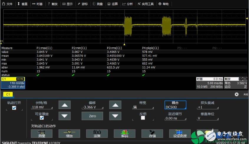
The 1:1 coaxial cable can reduce the path of signal transmission. In addition, the oscilloscope is directly set to 1:1 attenuation, which avoids the amplification of the oscilloscope noise by the software algorithm, thus bringing the most accurate measurement results.
The result of the coaxial cable test is 3.645V, which is 0.169V different than the measured value of 3.814V using the passive probe. It can be seen that when it is necessary to make very accurate measurements, coaxial cables should be selected for measurement to minimize measurement errors.
to sum upThis article mainly analyzes how to test the "high frequency switching power supply" noise from the perspective of testing. Through the above analysis, the following conclusions can be drawn:
1. According to the previous test method of high-frequency switching power supply ripple, directly selecting the bandwidth of 20MHZ for testing will not correctly reflect the true state of the high-frequency switching power supply. In the monitoring measurement of high-frequency switching power supply voltages such as this, other high-frequency noise interference should be considered, and the oscilloscope bandwidth cannot be limited to 20 MHz. To test a high-frequency switching power supply voltage fluctuation should choose what kind of bandwidth, to analyze the specific problem, to correctly determine whether to measure ripple or noise, correspondingly choose how to set up the oscilloscope.
2. If you need more accurate measurement, you need to reduce the error caused by the oscilloscope's 10:1 passive probe. It should be measured with a 1:1 attenuated coaxial cable.
Heated Seat Cushion,Portable Heated Seat Cushions,Heated Car Seat Cushion,Heated Seat Cushion Rechargeable
Ningbo Sinco Industrial & Trading Co., Ltd. , https://www.newsinco.com
