
1 How to create a bus
1) Menu place->bus or right shortcut button
2) Left mouse button in the schematic selects the starting point of the bus
3) Move the mouse to draw lines
4) If you need to turn, click the left mouse button to turn the page, the default is 90 degrees.
5) Double-click to end the bus
2 Place non-90 degree corner bus
1) Menu place bus
2) Hold shift, left-click to select the starting point
3) Drag the mouse to draw any angle bus
4) Click the left button to turn
5) Double-click to end the bus
3 bus naming
Naming rules: BUSNAME[0..31] or BUSNAME[0:31] or BUSNAME[0-31] three forms. Note that there must be no spaces between BUSNAME and '[', and BUSNAME cannot end with numbers. You cannot use names like BUSNAME00 BUSNAME02.
Place the net alias of the bus:
a) menu place ->net alias pops up place net alias dialog
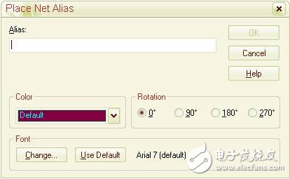
b) In accordance with the naming rules of the bus, enter in the alias column, OK.
4 bus and signal line connection
Place the bus entry bus entry, available menu place->bus entry or shortcut E or right shortcut button
Bus entry hangs on the mouse and press R to rotate the bus entry direction.
Move the Bus entry to the bus and click to place it.
Press hotkey F4 to repeat
Use wire to connect a pin to an entry in the bus.
Add net alias to wire, the naming rule is as follows: If the bus name is ED[0..31], the wire name must be such as ED0, ED1, ED2........ED31. Note that the network on which the wire is located is a member of the bus and cannot have square brackets.
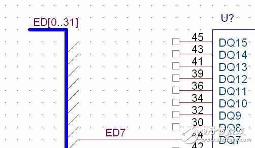
Hold down the CTRL key, mouse select wire, drag, connect other lines. At this point, the net alias on wire is automatically incremented.
Some explanations:
1) Electrical interconnection can only be achieved between the bus and the wire signal line via the network name.
2) If the bus line is not connected directly to the bus, the connection point is also shown at the connection, but no real electrical connection is made at this time. The bus must be interconnected via bus entry and signal lines. And the bus and signal lines must be named and conform to the naming rules.
3) If two busses form a T-connection, the connection points are automatically placed and electrically interconnected. The two cross-shaped buses have no connection points by default. To form electrical interconnections, the connection points must be placed manually.
LED Flashing Badge (LED Flashing pin)
Ningbo AST Industry Co.,Ltd has 17 Years Experiences to produce the Flashing Led Badge, Led Pins, Led Flashing Pins, Led Badges, Flashing Led Badges and so on .we can assure you of competive price,high quality,prompt delivery and technology supporting.
1. Flashing Led Badge Application:
The Led flashing Badges are usually used for Celebration,Party ,Warning and so on.
2.Press the play button to flash.
3.Led quantity and Led color:Customized.
4.Can be printed your logo on it
6.Certification:CE ,Rohs
7.Export to:
USA, UK,Canada,Germany, Turkey,Russia,Poland,Switzerland,Netherland ,Frence Hungary ,Australia,New Zealand, Brazil, Columbia,Argentina,Thainland,Singapore , Malaysia and so on.
  |
|
LED Flashing Badge, LED Flashing pin, Customizable led pin
AST Industry Co.,LTD , https://www.astsoundchip.com