The Hall sensor is a magnetic sensor. It can be used to detect magnetic fields and their changes, and can be used in a variety of applications related to magnetic fields. The Hall sensor is based on the Hall effect and is an integrated sensor consisting of a Hall element and its associated circuitry. The Hall sensor is a magnetic field sensor fabricated according to the Hall effect. The Hall effect is a kind of magnetoelectric effect. This phenomenon was discovered when Hall (AHHall, 1855-1938) studied the conductive mechanism of metal in 1879. Later, it was found that semiconductors, conductive fluids, etc. also have this effect, and the Hall effect of semiconductors is much stronger than that of metals. Various Hall elements made by this phenomenon are widely used in industrial automation technology, detection technology, information processing, etc. aspect.
As shown in FIG. 1, a control current I is applied across the semiconductor wafer, and a uniform magnetic field having a magnetic induction B of B is applied in the vertical direction of the sheet, and a potential difference of UH is generated in a direction perpendicular to the current and the magnetic field. Hall voltage,
The relationship between them is.
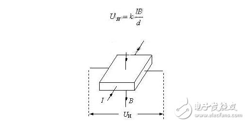
Where d is the thickness of the sheet, k is called the Hall coefficient, and its size is related to the material of the sheet. The above effect is called the Hall effect, which was discovered by the German physicist Hall in 1879 when studying the nature of current-carrying conductors in a magnetic field.
Hall sensorSince the potential difference generated by the Hall element is small, the Hall element is usually integrated with an amplifier circuit, a temperature compensation circuit, and a regulated power supply circuit on a chip, which is called a Hall sensor.
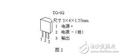
Hall sensors, also known as Hall ICs, have a small profile, as shown in Figure 2, which is an outline drawing of one of the models.
Classification of Hall sensorsHall sensors are classified into linear Hall sensors and switch Hall sensors.
(1) The switching Hall sensor consists of a voltage regulator, a Hall element, a differential amplifier, a Schmitt trigger and an output stage, which outputs a digital quantity. Switch-type Hall sensors also have a special form called a lock-type Hall sensor.
(2) The linear Hall sensor consists of a Hall element, a linear amplifier, and an emitter follower, which outputs an analog quantity.
Linear Hall sensors can be divided into open loop and closed loop. The closed-loop Hall sensor is also called a zero-flux Hall sensor. Linear Hall sensors are mainly used for AC and DC current and voltage measurements. .
Switch type
As shown in FIG. 4, Bnp is the magnetic induction intensity of the operating point "on", and BRP is the magnetic induction intensity of the release point "off". When the applied magnetic induction exceeds the operating point Bnp, the sensor outputs a low level. When the magnetic induction decreases below the operating point Bnp, the output level of the sensor does not change, and the sensor is lowered to the release point BRP. Jump to high level. The hysteresis between Bnp and BRP makes the switching action more reliable.
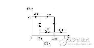
Lock type
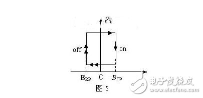
As shown in FIG. 5, when the magnetic induction exceeds the operating point Bnp, the sensor output transitions from a high level to a low level, and after the external magnetic field is cancelled, its output state remains unchanged (ie, a latched state), and an inverse must be applied. When the magnetic induction intensity reaches BRP, the level can be changed.
Linear type
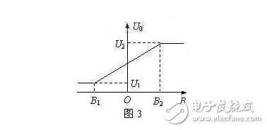
The output voltage has a linear relationship with the applied magnetic field strength. As shown in Fig. 3, it can be seen that there is a good linearity in the range of the magnetic induction intensity of B1 to B2, and the magnetic induction intensity is saturated when it exceeds this range.
Open loop current sensor
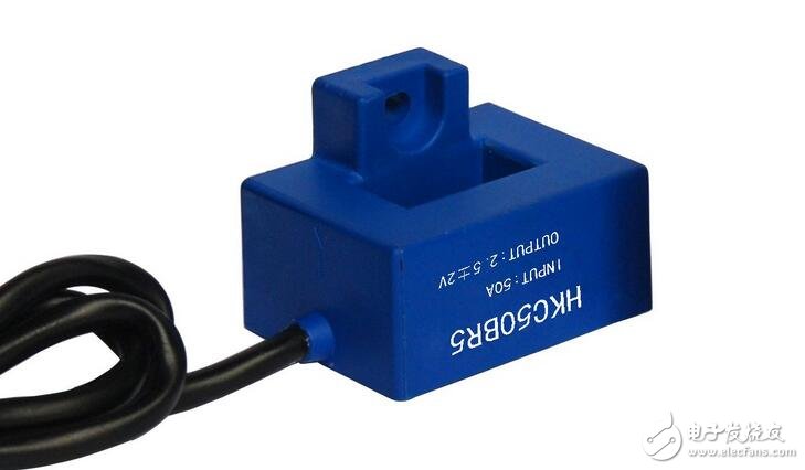
Since there is a magnetic field inside the energized solenoid, its magnitude is proportional to the current in the wire, so the Hall sensor can be used to measure the magnetic field to determine the current in the wire. Using this principle, a Hall current sensor can be designed. The advantage is that it does not make electrical contact with the circuit under test, does not affect the circuit under test, does not consume the power of the power source under test, and is particularly suitable for high current sensing.
The working principle of the Hall current sensor is shown in Fig. 6. The standard toroidal core has a notch, the Hall sensor is inserted into the notch, the coil is wound around the ring, and when the current passes through the coil, a magnetic field is generated, and the Hall sensor has a signal. Output.
Closed loop current sensor
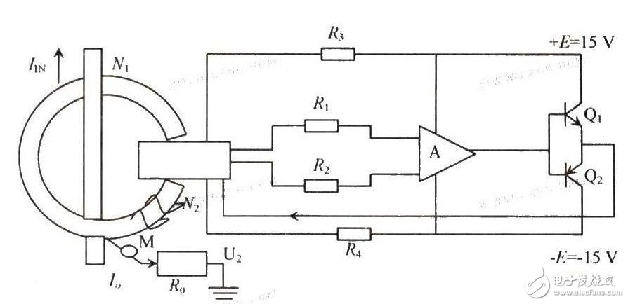
The magnetic balance type current sensor is also called the Hall closed-loop current sensor, also called the compensation type sensor, that is, the magnetic field generated by the main circuit measured current Ip at the collecting magnetic ring is compensated by a magnetic field generated by the current through a secondary coil, thereby The Hall device is in an active state of detecting zero flux.
The specific working process of the magnetic balance current sensor is: when a current flows through the main circuit, the magnetic field generated on the wire is collected by the collecting ring and sensed on the Hall device, and the generated signal output is used to drive the corresponding power tube and Turn it on to obtain a compensation current Is. This current then generates a magnetic field through a multi-turn winding that is exactly opposite to the magnetic field produced by the current being measured, thereby compensating for the original magnetic field and gradually reducing the output of the Hall device. When the magnetic field generated by multiplying Ip and the number of turns is equal, Is no longer increases. At this time, the Hall device functions to indicate zero magnetic flux, and can be balanced by Is at this time. Any change in the measured current will destroy this balance. Once the magnetic field is out of balance, the Hall device has a signal output. Immediately after power amplification, a corresponding current flows through the secondary winding to compensate for the unbalanced magnetic field. From the imbalance of the magnetic field to the rebalancing, the time required is theoretically less than 1 μs, which is a process of dynamic equilibrium.
1. current sensor
Since there is a magnetic field inside the energized solenoid, its magnitude is proportional to the current in the wire, so the Hall sensor can be used to measure the magnetic field to determine the current in the wire. Using this principle, a Hall current sensor can be designed. The advantage is that it does not make electrical contact with the circuit under test, does not affect the circuit under test, does not consume the power of the power source under test, and is particularly suitable for high current sensing.
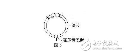
The working principle of the Hall current sensor is shown in Fig. 6. The standard toroidal core has a notch, the Hall sensor is inserted into the notch, the coil is wound around the ring, and when the current passes through the coil, a magnetic field is generated, and the Hall sensor has a signal. Output.
2. Displacement measurement
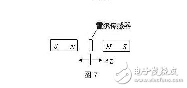
As shown in Figure 7, the two permanent magnets are placed opposite each other with the same polarity. The linear Hall sensor is placed in the middle, and its magnetic induction is zero. This point can be used as the zero point of the displacement. When the Hall sensor is on the Z axis, When Z is displaced, the sensor has a voltage output that is proportional to the magnitude of the displacement.
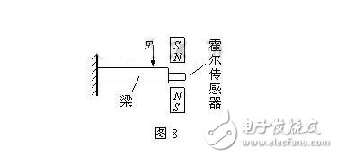
If the parameters such as tension and pressure are changed into displacement, the tensile force and pressure can be measured. As shown in Fig. 8, it is a force sensor made according to this principle.
b) Switch-type Hall sensors are mainly used for measuring the number of revolutions, speed, wind speed, flow rate, proximity switches, door closing informants, alarms, automatic control circuits, etc.
1. Measuring speed or number of revolutions
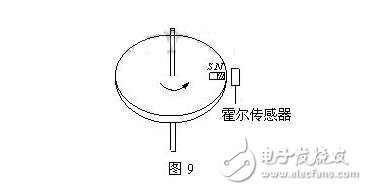
As shown in Fig. 9, a magnetic steel is adhered to the edge of the disc of the non-magnetic material, the Hall sensor is placed near the edge of the disc, and the disc is rotated one revolution, and the Hall sensor outputs a pulse, so that the rotation can be measured. Number (counter), if the frequency meter is connected, the speed can be measured.
If the switch-type Hall sensor is regularly arranged on the track at a predetermined position, a pulse signal can be measured from the measuring circuit when a permanent magnet mounted on the moving vehicle passes through it. The speed of movement of the vehicle can be measured based on the distribution of the pulse signal.
2. Various practical circuits
Switched Hall sensors are extremely versatile due to their small size, wide operating voltage range, reliable operation and low cost. Here are two practical circuits to illustrate:
Circuit 1 burglar alarm
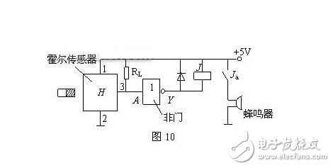
As shown in Figure 10, the small magnet is fixed on the edge of the door, and the Hall sensor is fixed on the edge of the door frame to bring the two closer together, that is, when the door is in the closed state, the magnet is close to the Hall sensor, and the output terminal 3 is low. Level, when the door is illegally opened, the Hall sensor output 3 is high, the non-gate output Y is low, the relay J is closed, Ja is closed, and the buzzer is powered and an alarm sounds.
Circuit 2 bus door status display
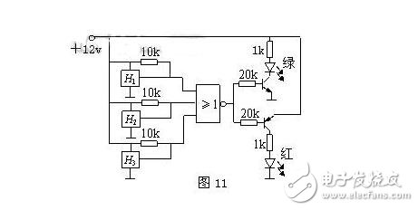
With the Hall sensor, it is easy to make an indicator that the door is closed by simply arranging a small permanent magnet. For example, the three doors of the bus must be closed before the driver can drive. The circuit is shown in Figure 11. Three switch-type Hall sensors are mounted on the three door frames of the car. Each piece of magnetic steel is fixed at the appropriate position of the door. When the door is open, the magnetic steel is away from the Hall switch, and the output is High level. If one of the three doors is not closed, the NOR gate output is low, and the red light is on, indicating that there is still a door that is not closed. If all three doors are closed, the NOR gate output is high. The green light is on, indicating that the door is closed and the driver can drive safely.
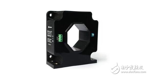
Hall sensor technology for the automotive industry
Hall sensor technology has a wide range of applications in the automotive industry, including power, body control, traction control and anti-lock braking systems. In order to meet the needs of different systems, Hall sensors are available in switching, analog and digital sensors.
Hall sensors can be made of metals and semiconductors. The quality of the effect depends on the material of the conductor. The material directly affects the positive ions and electrons flowing through the sensor. When manufacturing Hall elements, the automotive industry typically uses three semiconductor materials, namely gallium arsenide, indium antimonide, and indium arsenide. The most commonly used semiconductor material is indium arsenide.
The form of the Hall sensor determines the difference in the amplifying circuit and its output is adapted to the device being controlled. This output may be analog, such as an acceleration position sensor or a throttle position sensor, or it may be digital. Such as crankshaft or camshaft position sensor.
When a Hall element is used for an analog sensor, this sensor can be used for a temperature gauge in an air conditioning system or a throttle position sensor in a power control system. The Hall element is connected to a differential amplifier, which is connected to the NPN transistor. The magnet is fixed on the rotating shaft, and the magnetic field on the Hall element is strengthened when the shaft is rotated. The Hall voltage it produces is proportional to the strength of the magnetic field.
When a Hall element is used for a digital signal, such as a crankshaft position sensor, a camshaft position sensor or a vehicle speed sensor, the circuit must first be changed. The Hall element is connected to a differential amplifier, and the differential amplifier is connected to a Schmitt trigger. In this configuration. The sensor outputs an on or off signal. In most automotive circuits, the Hall sensor is a current sink or grounds the signal circuit. To do this, an NPN transistor is required to connect to the output of the Schmitt trigger. The magnetic field passes through the Hall element and the blades on one of the trigger wheels pass between the magnetic field and the Hall element.
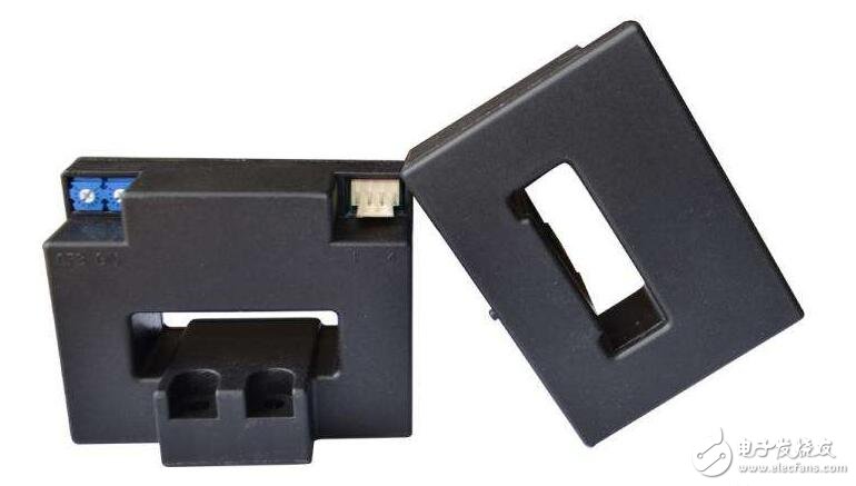
Hall sensor applied to taxi meter
The application of the Hall sensor on the taxi meter: the signal detected by the Hall sensor A44E mounted on the wheel is sent to the single chip microcomputer, processed and calculated, and sent to the display unit, thus completing the mileage calculation. The detection principle, P3.2 port as the input end of the signal, the internal use of external interrupt 0, each turn of the wheel (set the circumference of the wheel is 1 m), the Hall switch detects and outputs the signal, causing the interrupt of the microcontroller, Pulse counting, when the count reaches 1 000 times, that is, 1 km, the microcontroller will automatically increase the amount.
Whenever the Hall sensor outputs a low level signal, the MCU interrupts once. When the mileage counter counts the mileage pulse for 1 000 times, the program accumulates the current total amount, so that the microcomputer enters the mileage count interrupt service routine. In this program, the accumulation of the current mileage and total amount needs to be completed, and the result is stored in the mileage and total registers.
Application of Hall current sensor in frequency converter
A magnetic field is induced around a wire through which a current flows, and a Hall device is used to detect the magnetic field induced by the current, and the magnitude of the current generating the magnetic field can be measured. This makes it possible to form a Hall current and a voltage sensor. Because the output voltage of the Hall device is proportional to the product of the magnetic induction applied to it and the operating current flowing through it, it is a device with a multiplier function, and can directly interface with various logic circuits, and can also be directly driven. Loads of various natures. Because the application principle of the Hall device is simple, the signal processing is convenient, and the device itself has a series of unique advantages, it also plays a very important role in the inverter.
In frequency converters, the main role of Hall current sensors is to protect expensive high power transistors. Since the response time of the Hall current sensor is shorter than 1μs, when an overload short circuit occurs, the power supply can be cut off before the transistor reaches the limit temperature, so that the transistor can be reliably protected.
Hall current sensors can be divided into direct measurement type and zero magnetic formula according to their working modes. Because of the need for precise control and calculation in the inverter, the zero flux mode is selected. The output voltage of the Hall device is amplified, and then amplified by the current, the current is passed through the compensation coil, and the magnetic field generated by the compensation coil is opposite to the magnetic field generated by the current to be measured. If the condition IoN1=IsN2 is satisfied, the magnetic core The magnetic flux in is 0, then the following formula holds:
Io=Is(N2/N1)
Where, Io is the current to be measured, that is, the current in the primary winding in the core, N1 is the number of turns of the primary winding, Is is the current in the compensation winding, and N2 is the number of turns of the compensation winding. It can be seen from the above formula that when the magnetic balance is reached, Io can be obtained from Is and the turns ratio N2/N1.
Hall current sensors are characterized by "potential-free" detection of current. That is, the measurement circuit can realize current detection without having to access the circuit under test, and they are coupled by a magnetic field. Therefore, the input and output circuits of the detection circuit are completely electrically isolated. During the detection process, the detection circuit and the circuit under test do not affect each other.
Box Header Connector,Dual Row R-Type Box Header Connector,Box Header Straight Elevator Connector,Smt Box Header 2.0Mm Connector
Dongguan Yangyue Metal Technology Co., Ltd , https://www.yyconnector.com
