If you input a signal to one end of a transmission line, part of the signal will appear on adjacent transmission lines even if there is no connection between them. The coupling of signals through the surrounding electromagnetic fields creates noise, which is the source of crosstalk, and it will cause bit errors in the digital system. Once this noise appears on adjacent transmission lines, it will propagate as any other signal and will eventually be transmitted to the receiver at the end of the transmission line. Such crosstalk will affect the margin of noise that the receiver can withstand. In low-end analog applications, as little as 0.01% of crosstalk may be acceptable, and in high-speed digital applications, it can generally accept up to 5% of crosstalk.
Unfortunately, in many high-speed interconnect systems, the signal amplitude due to crosstalk can easily exceed the system's acceptable amplitude of 10%, which will increase the system's bit error rate. Quantitative measurement of the crosstalk size from the interference source transmission line to the victim transmission line is an important debugging method for identifying and eliminating possible sources of error.
The concept of S-parameters stems from the description of the microwave properties of interconnected devices or systems, providing the most intuitive method of describing crosstalk that exists in applications ranging from the audio range to the millimeter wave frequency range. After all, each parameter in the S-parameter matrix is ​​actually a comparison of a sinusoidal signal from one port output in the interconnect system to the other port input. In the transmission line structure, some parameters in the S parameter represent the direct measurement result of the crosstalk between the transmission line and the transmission line. It is also directly measurable in differential pairs.
Coupling transmission line test objectIn order to demonstrate how to use S-parameters to describe crosstalk, we designed a DUT consisting of four coupled transmission lines, as shown in Figure 1. Their end is identified as a number from 1 to 8. Connected to each end is a port that can be considered a 50 ohm transmission line termination. The port allocation when measuring the DUT is recommended by port 1 to port 2, 3 to 4, 5 to 6, and 7 to 8.
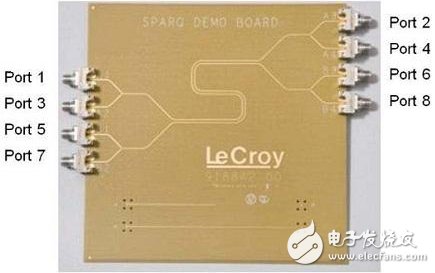
Figure 1, the four coupled transmission line pictures, the end of this example identifies the recommended port allocation number, each line about 11inch long when not winding
Each parameter in this DUT's S-parameter matrix is ​​the proportion of sinusoidal waveform input from one port and output from each other port. There are 8 ports with 8x8 = 64 different input and output combinations. The S-parameter matrix format facilitates the recording of each combination. The number of each parameter in the matrix indicates which is the input port and which is the output port. For example, S21 represents the ratio between the port 2 output and the port 1 input. This term is traditionally used to describe insertion loss. The physical meaning it represents is the attenuation of the signal as it passes through the channel.
As a ratio of two sinusoidal waveforms, each parameter in the S-parameter matrix is ​​a complex number, described by real and imaginary values ​​or amplitude and phase. The amplitude is the ratio of the output port waveform to the amplitude of the input port waveform. Typically, 50 ohms is used as the termination impedance for each port.
Most of the terms in the S-parameter represent direct measurements of crosstalk between ports. A sinusoidal waveform is input on port 1 of a transmission line. The crosstalk between the output of port 3 of the adjacent transmission line is identified as S31, and input from port 1 is correspondingly. The crosstalk output from port 4 is expressed as an S parameter matrix. S41.
The subtleties of crosstalkEven at low frequencies, the crosstalk between two adjacent transmission lines is related to which port the interfered transmission line is. Reverse transmission crosstalk is the sum of the coupled capacitance and inductance and forward transmission crosstalk is the difference between the coupled capacitance and inductance. In theory, S31 does not equal S41. Figure 2 shows the two parameters S31 and S41 measured using LeCroy's signal integrity network analyzer SPARQ. For example, at 20 MHz, the near-end crosstalk S31 and the far-end crosstalk S41 are different, and the near-end crosstalk S31 will be greater than the far distance. Crosstalk S41. This manifestation of the crosstalk signal in the interconnect system may be an intuitively opposite feature, even if S31 and S41 are crosstalk measured from the same interferer in the same interconnect system, each line on the interfered transmission line. The port noise is significantly different, especially above 100MHz.
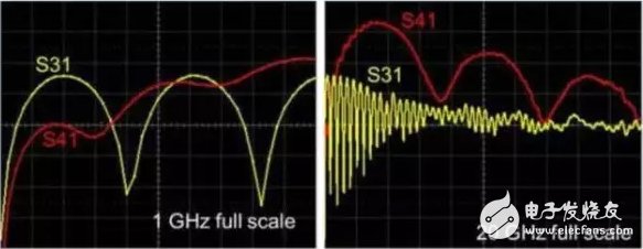
Figure 2. Measure crosstalk on adjacent transmission lines using LeCroy's SPARQ
Left: Horizontal axis full scale 1GHz Right: Horizontal axis full scale 20GHz Vertical scale is the same: full scale 40dB, top is 0dB
Just quantifying the noise appearing on the two transmission lines does not illustrate the problem well, but also quantifies the propagation direction of noise on the interfered transmission line, so the two-port sequence on the interfered transmission line should be identified separately, such as S31 and S13.
According to the S parameter identification, S31 denotes the noise of the interfered transmission line close to the source of interference, which is called near-end noise. The direction of signal transmission on the interferer is defined as positive, and the near-end noise is noise on the interfered transmission line and opposite to the signal transmission direction. S41 is the noise measured at the far end of the interfered transmission line and is positive. As shown in Fig. 1, the close-coupled microstrip transmission line has a -13 dB peak noise at the near-end, which corresponds to 22% of the erbium signal, and the far-end noise peak value can reach -4 dB, which is equivalent to 63% of the erbium signal. This large number indicates that the coupling between the two transmission lines is very tight.
S-parameters formally define which port is the input of the signal and which port is the output of the signal, which makes the S-parameter naturally suitable for describing crosstalk.
Using S-parameters to describe the frequency and time domain response of crosstalkAlthough S-parameters are based on sine wave behavior, for any linear passive time-invariant interconnect system, the behavior of any other waveform can be understood by understanding the behavior of the sine wave signal.
The common time domain waveform is a 0V to 1V step signal with a Gaussian rise time. The response of the interconnect system to each of the frequency components in the signal is described by S-parameters. Using mathematical operations, the step signal is converted to the frequency domain. Each frequency component is multiplied by the value of the corresponding frequency point in the S-parameter. The result is then converted to the time domain, that is, the DUT responds to a step signal, such as the use of a graph. The exact same frequency domain data in 2 is shown in Figure 3 but shown as a response to the step signal in the time domain. Near-end crosstalk and far-end crosstalk can be found to have very different characteristics. The mathematical operation can be used to change the rise time of the excitation signal to see what happens to the signal that is coupled to the adjacent disturbed transmission line.
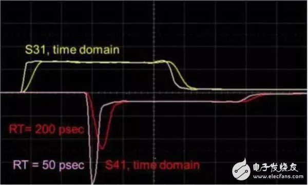
Figure 3, and the same crosstalk previously presented for adjacent disturbed transmission lines, but using a step signal as an input to the interference source transmission line in the time domain. The vertical scale is 10% cross-talk per square while the horizontal scale is 0.5ns per square.
In this example, the peak value of the near-end crosstalk S31 is not very sensitive to the rise time regardless of the corresponding change of 50ps or 200ps, but the far-end interference peak voltage is very sensitive to the change of the rise time, and the peak value rises with the increase of the time from -40. % changes to -25%.
The time domain display of the near-end and far-end crosstalk and the frequency domain display the same data, but the display mode is different. The flexibility of the mutual conversion between the time domain and the frequency domain facilitates us to quickly know the crosstalk noise waveform caused by some rise time step signal.
Crosstalk decreases with increasing coupling spacingThe S-parameter describes not only the coupling between any two conductors, but also the effect of the direction of signal propagation on crosstalk. Figure 4 shows the measured near-end crosstalk to other ports. As expected, the near-end noise of port 1 and another adjacent port is smaller as the port is further away from port 1.
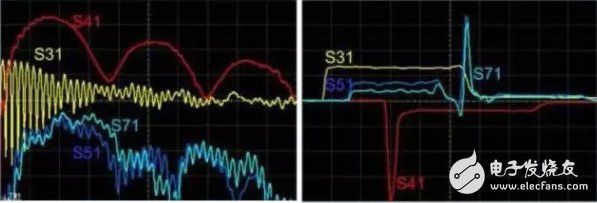
Figure 4. Frequency-domain (left) and time-domain (right) results of near-end crosstalk for the interference source transmission line and adjacent interfered-object transmission lines. The horizontal axis of the frequency domain waveform is full-scale 20 GHz, the vertical axis is 40 dB full scale, and the top is 0 dB. The horizontal axis of the time domain waveform is 0.5ns/div and the vertical axis is 10%/div. The time domain waveforms of S51 and S71 are magnified to 1%/div
Although near-end crosstalk drops as the port moves away from the source of interference, the frequency-domain response characteristics of the near-end noise and the far-end noise are more similar, but fall more clearly. Observing the time domain responses of S51 and S71 confirms that although the noise is measured at the near end, the response of S51 and S71 is mainly determined by the reflection of the peak glitch at the far end noise.
Differential responseThese four single-ended transmission lines can be considered as two differential pairs. In many high-speed digital applications, a differential pair is also often referred to as a channel. The signals of the differential pair are described as differential mode signals and common mode signals. S-parameters can be extended formally to various combinations of crosstalk between channels including a differential mode signal and a common mode signal of an interference source and an interfered object.
The test board of Figure 1 has 8 ports connected to 4 separate single-ended transmission lines as differential pairs, so that there are only 4 ports and 2 differential pairs in total. The differential port will be identified as differential port 1 to differential port 2 and differential port 3 to differential port 4 according to the single port port identification method.
The differential mode and common mode S-parameters are identified in a conventional manner, the differential mode signal is represented by the letter D, and the letter C is the common-mode signal. The combination of S-parameters output from one differential port input and the other differential port is identified as the letter of the output port mode, the letter of the input port mode, the output port, and the input port. E.g:
SDD31 represents near-end crosstalk between differential to differential mode signals.
SDD41 indicates far-end crosstalk between differential to differential mode signals.
SCC31 represents near-end crosstalk between common mode to common mode signals.
SDD41 indicates far-end crosstalk between differential to differential mode signals.
SCD31 indicates the crosstalk of the differential mode signal as a source of interference to the near-end common-mode signal.
The differential mode and common-mode crosstalk between channels and channels is shown in Figure 5, which clearly shows the advantages of tightly coupled differential channels in reducing crosstalk between channels.
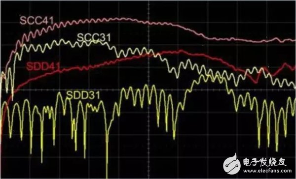
Figure 5: Differential mode and common-mode crosstalk between channels in the frequency domain: horizontal axis full-scale 20 GHz, vertical axis full-scale 80 dB, top 0 dB
Near-end and far-end crosstalk of differential-mode signals is 20 dB less than that of common-mode signals. This graphically illustrates why the differential signal reduces crosstalk more than a common-mode signal or a single-ended signal.
The crosstalk problem between high-speed signals is complex. It depends on which port of the interfering source channel is used as the signal input and which port of the interfered-through end is your viewing angle. It varies with the frequency and the way of change is complex. It will change due to the rise time. S-parameters have some natural features that facilitate the description of the complex behavior of crosstalk. Each parameter in the S-parameter matrix describes the crosstalk between any pair of ports and can be represented either in the time domain or in the frequency domain. They can be measured with a network analyzer or simulated with some simulation software. If crosstalk is an important issue in your design, you need to understand the concept of S-parameters!
1. The blades of an axial fan push air to flow in the same direction as the shaft. The impeller of an axial fan is similar to the propeller. When it works, most of the airflow is parallel to the shaft, in other words along the axis. When the inlet airflow is free air with zero static pressure, the axial flow fan has the lowest power consumption. When operating, the power consumption will increase as the airflow back pressure rises. Axial fans are usually installed in cabinets of electrical equipment, and sometimes integrated on motors. Because of their compact structure, they can save a lot of space and are easy to install, so they are widely used.
Its characteristics: high flow rate, medium wind pressure
2. Centrifugal fan
When the centrifugal fan works, the blades push air to flow in a direction perpendicular to the shaft (ie, radial), the air intake is along the axis direction, and the air outlet is perpendicular to the axis direction. In most cases, the cooling effect can be achieved by using an axial fan. However, sometimes if the airflow needs to be rotated by 90 degrees or when a larger wind pressure is required, a centrifugal fan must be used. Strictly speaking, fans are also centrifugal fans.
Its characteristics: limited flow rate, high wind pressure
3. Mixed flow fan
Mixed flow fans are also called diagonal flow fans. At first glance, mixed flow fans are no different from axial flow fans. In fact, the air intake of mixed flow fans is along the axis, but the air outlet is along the diagonal direction of the axis and the vertical axis. Because the blades and outer cover of this fan are called conical, the wind pressure is higher. Under the same size and other comparable performance, the centrifugal fan has lower noise than the axial fan.
Its characteristics: high flow rate and relatively high wind pressure
4-flow fan
Tubular wind flow can produce a large area of wind flow, which is usually used to cool large surfaces of equipment. The inlet and outlet of this fan are perpendicular to the axis (see Figure 1). The cross flow fan uses a relatively long barrel-shaped fan impeller to work. The diameter of the barrel-shaped fan blade is relatively large. Because of the large diameter, it can use a relatively low speed on the basis of ensuring the overall air circulation. , Reduce the noise caused by high-speed operation.
Its characteristics: low flow rate, low wind pressure
Axial Fan,Axial Flow Fan,Tube Axial Fan,Axial Exhaust Fan
Original Electronics Technology (Suzhou) Co., Ltd. , https://www.original-te.com
