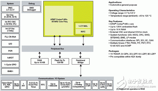
Freescale's KineTIs KEA128 series products are MCUs based on the ARM Cortex-M0 + core, operating frequency 48MHz, single-cycle 32-bit x32-bit multiplier, up to 128KB flash memory, 256B EEPROM and 16KB RAM, operating voltage 2.7V-5.5V, flash memory Write voltage 2.7V-5.5V, working temperature –40 ℃ C to + 125 ℃, mainly used in car entertainment connection module, DC / BLDC motor control, TPMS, electric motorcycle CDI / EFI, battery management, pump / fan control, Window / door / skylight control, BCM / HVAC and seat / wiper control, etc. This article introduces the main features and block diagram of KineTIs KEA128, as well as the main features, block diagram and circuit diagram of KEA128LEDLIGHTRD for automotive light control module
KineTIs EA series MCUs for automoTIve provide cost-effective ARM®-based solution for a wide range of automotive applications and are pin-compatible across the Kinetis EA series and with future Kinetis automotive families.
This series includes a set of analog, communication, timing and control peripherals with varying flash memory size and pin count. These scalable devices are highly robust, and offer an enhanced ESD / EMC performance solution for cost-sensitive automotive applications. This series is supported by development tools, software and hardware references to help you quickly start designing.
Operating Characteristics
• Voltage range: 2.7 to 5.5 V
• Flash write voltage range: 2.7 to 5.5 V
• Temperature range (ambient): –40 ℃ to + 125 ℃
Performance
• Up to 48 MHz ARM Cortex-M0 + core
• Single-cycle 32-bit x 32-bit multiplier
• Single-cycle I / O access port
Memories and Memory Interfaces
• Up to 128 KB flash
• Up to 256 B EEPROM
• Up to 16 KB RAM
Clocks
• Oscillator (OSC) —loop-controlled Pierce oscillator, crystal or ceramic resonator range of 31.25 kHz to 39.0625 kHz or 4 MHz to 24 MHz
• Internal clock source (ICS) —internal FLL with internal or external reference, precision trimming of internal reference allowing 1% deviation across temperature range of –30 ℃ to 85 ℃ and 1.5% deviation across temperature range of –40 ℃ to 125 ℃, up to 48 MHz
• Internal 1 kHz low-power oscillator (LPO)
System Peripherals
• Power management module (PMC) with three power modes: run, wait, stop
• Low-voltage detection (LVD) with reset or interrupt, selectable trip points
• Watchdog with independent clock source (WDOG)
• Programmable cyclic redundancy check module (CRC)
• Serial wire debug interface (SWD)
• Bit manipulation engine (BME)
Security and Integrity Modules
• 80-bit unique identification (ID) number per chip
Human-machine interface (HMI)
• Up to 71 general-purpose input / output (GPIO)
• Up to two 32-bit keyboard interrupt modules (KBI)
• External interrupt (IRQ)
Analog Modules
• One 12 bit with up to 16 channel SAR ADC with internal band gap reference channel, operation in stop mode, optional hardware trigger (ADC)
• Two analog comparators containing a 6-bit DAC and programmable reference input (ACMP)
Timers
• One 6-channel FlexTimer / PWM (FTM)
• Up to two 2-channel FlexTimer / PWM (FTM)
• One 2-channel periodic interrupt timer (PIT)
• One real-time clock (RTC)
• Up to one 16-bit pulse width timer
• Infotainment connection module
• Park assistance
• DC / BLDC motor control
• Electronic park brake
• TPMS
• Motorcycle CDI / EFI
• Battery management
• Pump / fan controller
• Passive entry push start
• Ambient lighting
• BCM / HVAC
• Windows / door / sun roof
• Seats / mirror / wiper
• Immobilizer
• Powertrain companion chip
• Generic sensor node

Figure 1. Kinetis KEA128 series MCU block diagram
KEA128LEDLIGHTRD: Light Control Module Reference Design Based on Kinetis EA MCU and E-switch (MC10XS3425)
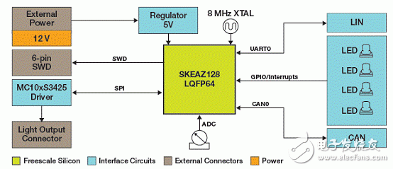
The lighting control reference design is built on a Kinetis KEA128 32-bit ARM® Cortex®-M0 + automotive-grade MCU. Overall hardware solution includes Kinetis KEA128 MCU, MC10XS3425EK quad high-side driver chips MC33901 CAN transceiver and MC33662 LIN transceiver chips. This covers LIN and CAN communication-based complete headlight environment control solution, including LEDs, tail lights, turn signals, lamp current control and diagnostics.
Hardware board is available for purchase to evaluate this solution and it includes a SWD connector interface to debug the SW provided. In addition, a lighting connector interface is available to increase the number of lights controlled through this solution.
32-bit KEA128 MCU in 64 LQFP package
MC33662 LIN transceiver
MC33901 CAN transceiver
MC10XS3425EK multi-chip high-side switch
4 LEDs
4 Potentiometers
4 User buttons
SWD connector interface for debugging
Light connector interface
The KEA128LEDLIGHTRD light control module reference design includes:
• Kinetis KEA128LEDLIGHTRD board
• DVD
• Quick Start Guide

Figure 2. KEA128LEDLIGHTRD light control module reference design block diagram

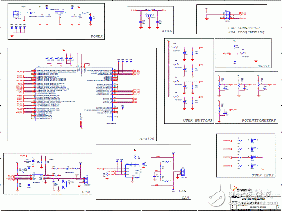
Figure 3. KEA128LEDLIGHTRD light control module reference design circuit diagram (1)

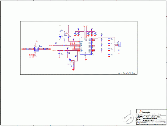
Figure 4. KEA128LEDLIGHTRD light control module reference design circuit diagram (2)
ECU Connector Section.
ECU-MEM-CONNECTOR is used to connect the ECU-MEM to the DIAG-LAYER. This part of ODX also links the ECU-MEM-objects with DIAG-COMMS e.g. used to read idents, download or upload the data. It allows an ECU to be flashed using ODX.
There are nearly 100 kinds of connectors used in general automobiles, and hundreds of connectors are used in a single vehicle model. With the increasing demand for automobile safety, environmental protection, comfort and intelligence, the application of automotive electronic products is increasing, which will make the number of Automotive Connector applications increase.
Four basic structural components of automobile connector
1. Contact
It is the core part of automobile connector to complete the electrical connection function. Generally, the contact pair is composed of positive contact and negative contact, and the electrical connection is completed by inserting the female and male contacts. The positive contact is a rigid part, and its shape is cylindrical (round pin), square cylinder (square pin) or flat (insert piece). The positive contact is generally made of brass and phosphor bronze.
The female contact, namely jack, is the key part of the contact pair. It relies on the elastic structure to produce elastic force due to elastic deformation when it is inserted with the pin, and forms a close contact with the positive contact to complete the connection. There are many kinds of Jack structures, such as cylinder type (split slot, shrink mouth), tuning fork type, cantilever beam type (longitudinal slot, 9-shaped), box type (square socket) and hyperboloid linear spring jack.
2. Shell
Also known as the shell, it is the cover of automobile connector, which provides mechanical protection for the built-in insulation mounting plate and pin, and provides the alignment of plug and socket when inserting, so as to fix the connector to the equipment.
3. Insulator
Insulator is also called automobile connector base or insert. Its function is to arrange the contact according to the required position and spacing, and to ensure the insulation performance between contacts and between contact and shell. Good insulation resistance, voltage resistance and machinability are the basic requirements for selecting insulating materials to be processed into insulators.
4. Annex
Accessories are divided into structural accessories and installation accessories. Structural accessories such as snap ring, locating key, locating pin, guide pin, connecting ring, cable clamp, sealing ring, sealing gasket, etc. Install accessories such as screws, nuts, screws, coils, etc. Most accessories have standard parts and general parts. It is these four basic structural components that enable the automotive connector to act as a bridge and operate stably.
Application characteristics of automotive connector
From the use purpose of the automobile connector, in order to ensure the better driving of the car, we can divide the reliability of the connector into the sealing property in use and the fireproof performance in the driving of the car. In addition, in the driving of the car, the connector can also show the shielding performance and temperature control performance. In general, when discussing the sealing property of automobile connector, the sealing performance of automobile connector is not only for water.
In this field, the current international management standard is IP67, which is also the highest level in the automotive closure industry. Although the waterproof requirements are different in different parts of the car, many automobile manufacturers will choose IP67 to ensure the airtight performance of their car connectors.
In the driving of the car, power supply is a very important energy source, not only related to the normal work of the engine, but also often involved in the use of power supply in the process of driving. Therefore, in the automotive power system, the automotive connector has different division, between the male connector and the equipment, between the male connector and the cable, between the male and female connector, and between the female connector and cable, there are certain sealing measures that can be implemented.
Sealing ring is a common tool in the sealing performance of automotive connector. This tool can not only achieve the effect of fixing between different hole positions, but also achieve the sealing effect. It can not only ensure the stable operation of automobile equipment, but also ensure the waterproof performance of automobile equipment in work. Most of the sealing rings are made of silicone rubber, which is made of liquid silicon and solid silicon after certain chemical changes.
Now the car is in use, electronic circuit technology is an important aspect of the automotive industry, not only in the driver's entertainment, but also in the driver's driving car control system, electronic circuit technology plays an important role in the stable work of the car. In order to ensure the stable work of electronic circuit technology, people have applied a lot of shielding technology in automobile production.
These shielding technologies not only play a protective role in the electronic circuit of the automobile, but also have the ability of anti-interference and anti radiation in the parts of the car. In addition, they can also play a protective role for the stable work of the automobile connector. These can be divided into two types of external shielding and internal shielding.
When using external shielding to protect automobile connector, two identical shielding shells are usually assembled together to form a shielding layer, and the length of the shielding layer can cover the whole length of the connector. On the shielding layer shell, there should be enough locking plate structure to ensure the reliable installation of the shielding layer. In addition, the shielding materials used should not only be treated by electroplating, but also be treated to prevent chemical corrosion.
The future trend of automotive connector
At present, the global automotive connector industry accounts for about 15% of the connector industry. In the future, it is expected to take a larger proportion under the drive of automotive electronic products. In terms of product cost structure, the average cost of connectors used in each car in China is only a few hundred yuan, compared with that of foreign countries
ECU Connector Section
ShenZhen Antenk Electronics Co,Ltd , https://www.antenkelec.com
