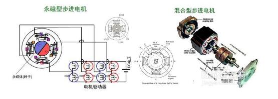
Most of the stepping motors currently used in computerized embroidery machines are three-phase hybrid stepping motors, and the subdivision driving technology can greatly improve the running quality of stepping motors, reduce torque ripple, suppress oscillation, reduce noise, and improve steps. Moment resolution.
First, the stepper motor is mainly used in some occasions with positioning requirements, such as: wire cutting workbench drag, planting machine workbench (pores positioning), packaging machine (fixed length), basically involving positioning occasions Use it.
Second, it is widely used in ATM machines, inkjet printers, cutting plotters, photo machines, spraying equipment, medical instruments and equipment, computer peripherals and mass storage equipment, precision instruments, industrial control systems, office automation, robots, etc. Applications requiring smooth operation, low noise, fast response, long life and high output torque.
Third, the stepping motor has a wide range of applications in textile machinery such as computer embroidery machines. The characteristics of this type of stepping motor are that the torque is not high, the reaction speed is fast, the running noise is low, the operation is stable, and the control performance is good. The whole machine costs are low.
Stepper motor application notes1. Stepper motor is used in low-speed occasions---the speed per minute does not exceed 1000 rpm, (6666PPS at 0.9 degrees), preferably between 1000-3000PPS (0.9 degrees), which can be used to work here through the reduction gear. At this time, the motor has high working efficiency and low noise.
2. It is better not to use the whole step state of the stepping motor, and the vibration is large in the whole step state.
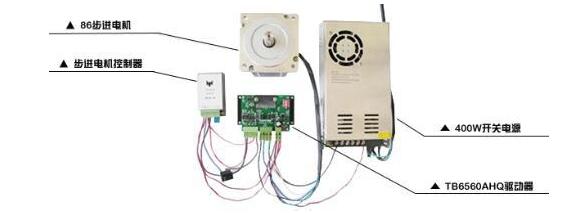
3. For historical reasons, only the motor with the nominal 12V voltage uses 12V. The voltage value of other motors is not the driving voltage volt value. The driving voltage can be selected according to the driver (recommended: 57BYG uses DC 24V-36V, 86BYG uses DC 50V, 110BYG uses 80V higher than DC. Of course, 12V voltage can be used in addition to 12V constant voltage drive. Other drive power can be used, but temperature rise should be considered.
4. The load with large moment of inertia should choose the motor with large frame size.
5. When the motor is at a high speed or a large inertia load, it is generally not started at the working speed, but the speed is increased by gradually increasing the frequency, and the motor does not lose the step. Secondly, the noise can be reduced and the positioning accuracy of the stop can be improved.
6. When high precision is used, it should be solved by mechanical deceleration, increasing the speed of the motor, or by using a driver with high subdivision number. It is also possible to use a 5-phase motor, but the whole system is more expensive, fewer manufacturers, and it is eliminated. The argument is a layman.
7. The motor should not work in the vibration zone. If it must be solved by changing the voltage, current or adding some damping.
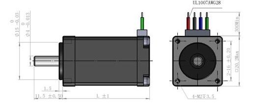
8. The motor works below 600PPS (0.9 degrees) and should be driven by small current, large inductance and low voltage.
9. The principle of selecting the motor after selecting the motor should be followed.
Four stepper motor circuit diagram circuit diagram 1: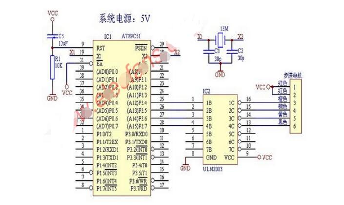
The connection circuit diagram of the stepping motor drive circuit and the 51 single chip microcomputer is as above;
The drive signal of the stepper motor must be a pulse signal! The speed of rotation is proportional to the frequency of the pulse,
The stepping motor has a step angle of 7.5 degrees. A 360 degree circle requires 48 pulses to complete (the figure above replaces the stepper motor with a 6-pin terminal block).
Group A (that is, the third pin of the stepper motor in the above figure) coil corresponds to P2.4;
Group B (that is, the fourth pin of the stepper motor in the above figure) corresponds to P2.5;
Group C (that is, the fifth pin of the stepper motor in the above figure) corresponds to P2.6;
Group D (that is, the sixth pin of the stepper motor in the above figure) corresponds to P2.7;
Forward rotation order: AB group - BC group - CD group - DA group (ie one pulse, forward 7.5 degrees).
Circuit diagram 2:Stepper motors have the characteristics of fast start-stop and precise positioning. Stepper motors are often used as position control actuators in the field of digital control. In fast operation, the stepper motor requires the drive circuit to provide the drive current of the stepper motor winding as close as possible to the value required by its specifications to generate sufficient torque. Since the stepper motor is an inductive load, when the operating speed is increased, the operating current of the winding is increased, and the power supply voltage must be increased. In practical applications, the commonly used control method is high and low voltage constant current chopper control. In the process of transforming the grinding machine to the northwest bearing factory, the author designed a practical stepping motor drive circuit, which can drive the three-phase six-shot reactive stepping motor of four models of 75BF003-130BF003, the maximum operating frequency is 15000 per minute. step. In addition to the characteristics of constant current chopping, the circuit also has overcurrent protection and over temperature protection.
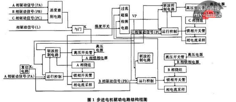
The road (Fig. 1) consists of a speed discrimination circuit, an overcurrent overtemperature detection circuit, A, B, and C phase drive circuits and a power supply. In this circuit, the A-phase drive signal (PA), the B-phase drive signal (PB), the C-phase drive signal (PC), and the phase-locked drive signal (L) output by the single-chip microcomputer are all active low. The high-voltage power supply for driving the stepping motor is supplied by AC70V rectification and filtering, and the phase-locked power supply is supplied by AC4.5V half-wave rectification. In addition, the +12V and +5V DC voltages required by the circuit are obtained by rectifying and filtering the AC10V and AC5V through diodes. The power required by the digital circuit is provided by the host through the inter-board interface J401. 2 part of the circuit introduction 2.1 speed discriminating circuit The core of the discriminating circuit is a retriggerable monostable CD4538 (Figure 2). When the single-chip microcomputer controls the stepper motor to operate, first set the phase-locked drive signal L to a high-level, and then PA, PB, and PC follow A→AB→B→BC→C→CA→A (or AC→C→BC). The sequence of →B→AB→A→AC) alternately appears in a low level, thereby driving the stepping motor to run step by step. Since at least one of the PA, PB, and Pc signals will have a transition (rising or falling edge) during operation, this transition is caused by resistors and capacitors (such as R470, C411, R471, R490, and D431). The differential circuit formed becomes a negative pulse applied to the input terminal of the 8-input NAND gate U409, and a positive pulse is triggered at its output to monostable U408A; the output Q of the U408A and the phase-locked drive signal L pass through the switch The parallel circuit formed by the diodes D473 and D474 controls the chopper circuits of the A, B, and C three-phase driving circuits. Since the transient time of U408A is about 1S, when the running speed of the stepping motor is lower than 1 step per second, the speed discriminating circuit first outputs a high level of about 1S, so that each phase driving circuit performs a constant current of about 1S. The chopper action causes the stepper motor to be in place quickly and then goes to the phase-locked state (the current of each phase of the stepper motor drops to approximately half of its operating current) to reduce the power consumption of the stepper motor.
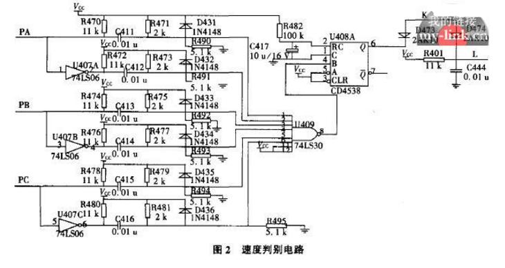
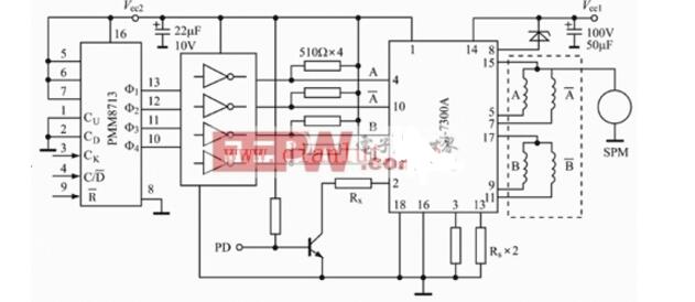
Figure 4 four-phase stepper motor power drive circuit
The output frequency of the LM331 and the input voltage have the following relationship: f0=Vi/(IRt1RL), where t1 is determined by the external timing elements Rt and Ct, t1=1.1RtCt, IR is provided by the internal precision current source, IR=1.9V/RS . Therefore f0=ViRS/(2.09RtRLCt). RS is an adjustable resistor whose function is to adjust the gain deviation of the LM331. Ct is a filter capacitor, generally 0.01~0.1μF. When the filtering effect is good, a 1μF capacitor can be used. In order to improve accuracy and stability, the component is selected from low temperature coefficient devices. The application example uses a PMM8713 stepper motor ring distributor and SI7300A stepper motor power amplifier to design a four-phase stepper motor power drive circuit. The PMM8713 adopts single pulse input and 1-2 phase excitation mode. The circuit is shown in Figure 5. In the figure, the PD control terminal is the input current I0 regulation terminal of SI7300A, which can be suspended or connected to a high level. When connected to a high level, the output current I0 of the SI7300A can be appropriately increased, which is suspended in the application system. The clock input signal of the PMM8713 is output by the LM331 (V/F), and the direction control signal and the start and stop signals of the stepper motor are given by the window comparison circuit.
Circuit diagram four:This paper introduces the design of two kinds of unipolar and bipolar drive circuits which are most commonly used by BYG universal series two-phase stepping motor. It shows the control method of two-phase stepping motor in principle and increases the stepping motor drive circuit. Design flexibility. The unipolar and bipolar two-drive circuit design of the two-phase stepping motor adopts a single-chip AT89S52 which can be programmed online as the controller. The circuit composed of the Darlington power tube TIP142 acts as the driver, and the circuit structure is simple and designed. Clear thinking.
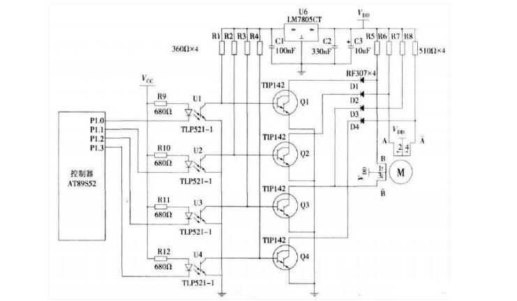
Unipolar drive circuit diagram 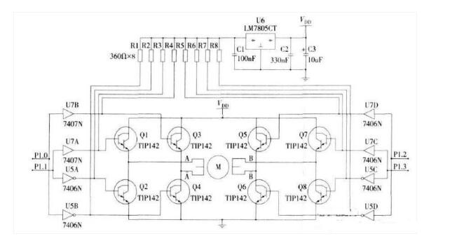
Bipolar drive circuit diagram
Industrial and Medical Display
There are many kinds of LCD classification standards, which can be divided into passive matrix and active matrix according to the driving mode
Passive matrix: Passive matrix LCD can be divided into TN-LCD(TwistedNematic LCD), STN-LCD(SuperTN-LCD) and DSTN-LCD(Doublelayer STN-LCD).
Active matrix: Active matrix LCD, also known as TFT-LCD, is widely used at present. Tft-lcd is short for thin-filmliquid-Crystal Display
The TFT-thin Film Transistor
Liquid Crystal Display
Short for TFT-LCD Liquid-CrystalDisplay
Tft-lcd has been widely used in various display equipment due to its advantages of small size, light weight, low radiation, low power consumption and full color.
Functions of TFT-LCD structure
(1) Backlight plate module: provide the source of light;
(2) Upper and lower polarizing plates, TFT Glass Substrate, liquid crystal: forming polarized light, controlling the passage of light;
(3) Color filters: Provide TFT LCD red, green and blue (three primary colors of light) sources;
(4) ITO transparent conductive layer: provide transparent conductive path;
(5) Photo Spacer: Provide a fixed height for color filters and TFT Glass Substrate. As a space for liquid crystal infusion, and as a support for the upper and lower Glass layers.
Medical Display,Medical Lcd Monitor,Medical Monitor,Medical Grade Monito
TONYA DISPLAY LIMITED , https://www.tydisplay.com
