First, the resistance
The resistor is represented by a "R" plus a number in the circuit, such as: R13 represents a resistor numbered 13. The main role of the resistor in the circuit is shunt, current limit, voltage divider, bias, filtering (combined with capacitors) and impedance matching.
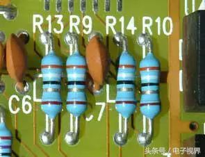
Resistor symbol
Parameter identification: The unit of resistance is ohm (Ω), and the unit of magnification is: kilo ohm (KΩ), megohm (MΩ) and so on. The conversion method is: 1 megaohm = 1000 kohm = 1000000 ohm resistance There are three kinds of parameter labeling methods, namely, the direct label method, the color scale method and the number standard method.
1MΩ=1000KΩ=1000000Ω
The digital standard method is mainly used for small-sized circuits such as patches, such as: 103 means 10000Ω (10 followed by 3 0), that is, 10K
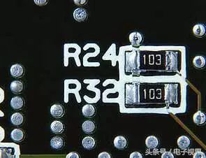
Chip resistance identification
The color ring labeling method is the most used, and the following examples are as follows:
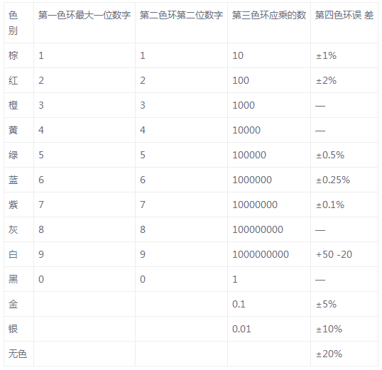
The resistance and error of the carbonaceous resistor and some 1/8 watt carbon film resistors are represented by color circles. There are three or four color rings on the resistor. Close to the resistance end is the first color ring, and the rest are two, three, and four color rings, as shown in Figure 1. The first color ring represents the largest digit of the resistance, the second color ring represents the second digit, and the third color ring indicates that the resistance should not have a few zeros. The fourth color circle represents the error of the resistance. The numbers or meanings represented by the color of the color ring are shown in Table 1.
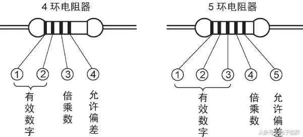
Representation method of color ring resistor
Table 1 The number or meaning represented by the color of the color circle
For example, there is a carbon resistor, which has four color rings in the order of red, black, red, and gold. The resistance of this resistor is 2000 ohms with an error of ± 5%. As shown below.

Red, black, red, gold. The resistance is 2000 Euro = 2k
For example, there is a carbon resistor, which has three color circles of brown, green and black. Its resistance is 15 ohms and the error is ±20%.
Color ring resistance is the most common type of resistor used in various electronic devices. No matter how it is installed, the repairer can easily read the resistance value for easy detection and replacement. However, in practice, it has been found that some color ring resistors are not clearly arranged in order, and are often easy to read. In recognition, the following techniques can be used to judge:
Tip 1: First find the color ring of the mark error, and then arrange the color ring order. The most commonly used colors for resistance errors are: gold, silver, brown, especially gold rings and silver rings, which are rarely used as the first ring of the resistance color ring, so as long as there are gold rings and silver rings in the resistance, It can be basically assumed that this is the last ring of the color ring resistance.
Tip 2: Whether the brown ring is the discriminant of the error sign. The brown ring is often used as an error loop, and often as an effective digital ring, and often appears in both the first ring and the last ring, making it difficult to identify who is the first ring. In practice, it can be discriminated according to the interval between the color rings: for example, for the resistance of a five-color ring, the interval between the fifth ring and the fourth ring is smaller than the interval between the first ring and the second ring. To be wider, it is possible to determine the order in which the color rings are arranged.
Tip 3: In the case where the color circle interval cannot be determined by the color circle spacing alone, the production sequence value of the resistor can also be used for discrimination. For example, the color ring reading order of a resistor is: brown, black, black, yellow, brown, and its value is: 100×10000=1MΩ, the error is 1%, which belongs to the normal resistance series value. If it is reverse order reading: brown, yellow , black, black, brown, the value is 140 × 1 Ω = 140 Ω, the error is 1%. Obviously, the resistance values ​​read out in the latter order are not found in the production series of resistors, so the latter color ring sequence is incorrect.
Second, the capacitor
1. The capacitor is generally represented by a "C" plus a number in the circuit (for example, C223 represents a capacitor numbered 223). The capacitor is an element consisting of two metal films abutting and separated by an insulating material. The characteristics of the capacitor are mainly DC-blocking AC.
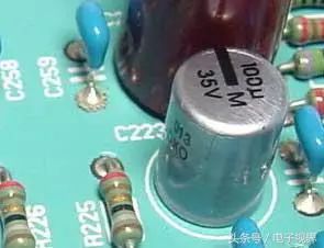
Capacitor on the board
The size of the capacitor capacity is the size of the energy that can be stored. The blocking effect of the capacitor on the AC signal is called capacitive reactance, which is related to the frequency and capacitance of the AC signal.
Capacitive reactance XC=1/2Ï€f c (f indicates the frequency of the AC signal, C indicates the capacitance capacity)
Common types of capacitors used in telephones are electrolytic capacitors, ceramic capacitors, chip capacitors, monolithic capacitors, tantalum capacitors, and polyester capacitors.
2. Identification method: The identification method of the capacitance is basically the same as the identification method of the resistance, and there are three types: the direct label method, the color scale method and the number standard method. The basic unit of the capacitance is pulled (F), and other units are: millifarad (mF), microfarad (uF), nanofarad (nF), and picofarad (pF).
Among them: 1 Farad = 103 millifarads = 106 microfarads = 109 nanofarads = 1012. Capacitance capacity is large. The capacitance value is directly indicated on the capacitor. For example, a capacitor with a small capacity of 10 uF/16V has a capacity value on the capacitor. Representation or numerical representation.
Letter notation: 1m=1000 uF 1P2=1.2PF 1n=1000PF
Digital notation: Generally speaking, the three-digit number indicates the capacity. The first two digits represent the significant digits and the third digit is the magnification.
For example: 102 means 10×102PF=1000PF 224 means 22×104PF=0.22 uF
3, capacitance capacity error table

For example, a ceramic capacitor having a capacitance of 104 J indicates a capacity of 0.1 uF and an error of ±5%.
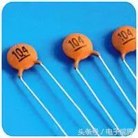
104 ceramic capacitor
4, fault characteristics
In actual maintenance, the main faults of the capacitor are:
(1) Open circuit fault caused by pin corrosion.
(2) Open circuit failure of desoldering and virtual welding.
(3) A small capacity or open circuit failure after leakage.
(4) Leakage, severe leakage and breakdown failure.
Third, the crystal diode
The crystal diode is usually represented by a "D" plus a number in the circuit, such as: D7 represents a diode numbered 7.
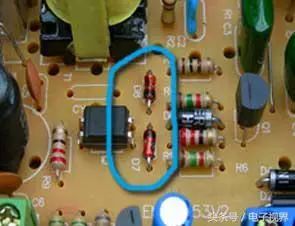
Representation of diodes in circuits
1. Function: The main characteristic of the diode is unidirectional conductivity, that is, the on-resistance is small under the action of the forward voltage; and the on-resistance is extremely large or infinite under the action of the reverse voltage. Because diodes have the above characteristics, they are often used in cordless telephones in circuits such as rectification, isolation, voltage regulation, polarity protection, code control, frequency modulation, and squelch.
Crystal diodes can be divided into rectifier diodes (such as 1N4004), isolation diodes (such as 1N4148), Schottky diodes (such as BAT85), light-emitting diodes, and Zener diodes.
2. Identification method: The identification of the diode is very simple. The N pole (negative pole) of the small power diode is mostly marked with a color circle on the outer surface of the diode. Some diodes also use the special symbol of the diode to indicate the P pole (positive pole) or N pole. (Negative electrode), also using the symbol marks "P", "N" to determine the polarity of the diode. The positive and negative poles of the LED can be identified by the length of the pin, the long leg is positive and the short leg is negative.
3. Test Note: When using a digital multimeter to measure the diode, the red pen is connected to the positive pole of the diode, and the black test lead is connected to the negative pole of the diode. The resistance measured at this time is the forward conduction resistance of the diode, which is analog with the pointer. The multimeter's test leads are just the opposite.
Semiconductor diodes are used in almost all electronic circuits. They play an important role in many circuits. They are one of the earliest semiconductor devices and are widely used.
How the diode works
The crystal diode is a pn junction formed by a p-type semiconductor and an n-type semiconductor, and a space charge layer is formed on both sides of the interface, and a self-built electric field is built. When there is no applied voltage, the diffusion current caused by the difference in carrier concentration on both sides of the pn junction is equal to the drift current caused by the self-built electric field, and is in an electrical equilibrium state.
When the outside has a forward voltage bias, the mutual suppression of the external electric field and the self-built electric field causes the diffusion current of the carrier to increase to cause a forward current.
When the outside has a reverse voltage bias, the external electric field and the self-built electric field are further strengthened to form a reverse saturation current I0 that is independent of the reverse bias voltage value within a certain reverse voltage range.
When the applied reverse voltage is high to a certain extent, the electric field strength in the space charge layer of the pn junction reaches a critical value to generate a multiplication process of carriers, generating a large number of electron hole pairs, and generating a large reverse breakdown current. It is called the breakdown phenomenon of the diode.
Type of diode
There are many types of diodes, which can be classified into germanium diodes (Ge tubes) and silicon diodes (Si tubes) depending on the semiconductor material used. According to its different uses, it can be divided into detection diodes, rectifier diodes, Zener diodes, switching diodes, etc. According to the die structure, it can be divided into point contact diodes, surface contact diodes and planar diodes.
The point contact diode is pressed on the surface of a clean semiconductor wafer with a very thin wire, and a pulse current is passed so that one end of the contact wire is firmly sintered with the wafer to form a "PN junction". Due to the point contact, it is only allowed to pass a small current (not more than tens of milliamps), and is suitable for high frequency and small current circuits, such as radio detection.
The "PN junction" area of ​​the surface contact type diode is large, allowing a large current (a few amps to several tens of amps) to be used, mainly for converting the alternating current into a "rectifying" circuit of direct current.
The planar diode is a special type of silicon diode that not only passes large current, but also has stable and reliable performance. It is widely used in switching, pulse and high frequency circuits.
Diode's conductive properties
The most important characteristic of a diode is its unidirectional conductivity. In the circuit, current can only flow from the positive pole of the diode and the negative pole flows out. The forward and reverse characteristics of the diode are illustrated by simple experiments.
Forward characteristic
In the electronic circuit, the positive pole of the diode is connected to the high potential end, the negative pole is connected to the low potential end, and the diode is turned on. This connection method is called forward biasing. It must be stated that when the forward voltage applied across the diode is small, the diode is still not conducting, and the forward current flowing through the diode is very weak. Only when the forward voltage reaches a certain value (this value is called "threshold voltage", the xenon tube is about 0.2V, and the silicon tube is about 0.6V), the diode can be turned on. The voltage across the diode remains essentially constant after conduction (the transistor is approximately 0.3V and the silicon tube is approximately 0.7V) and is referred to as the "forward voltage drop" of the diode.
Reverse characteristic
In the electronic circuit, the positive pole of the diode is connected to the low potential end, and the negative pole is connected to the high potential end. At this time, almost no current flows in the diode, and the diode is in an off state. This connection method is called reverse bias. When the diode is reverse biased, there is still a weak reverse current flowing through the diode, called the leakage current. When the reverse voltage across the diode increases to a certain value, the reverse current will increase sharply and the diode will lose its unidirectional conduction characteristics. This state is called diode breakdown.
Main parameters of the diode
A specification used to indicate the performance and range of a diode, called the diode's parameters. Different types of diodes have different characteristic parameters. For beginners, you must understand the following main parameters:
1, rated forward working current
It is the maximum forward current value that the diode is allowed to pass when it is continuously operated for a long time. When the current passes through the tube, the die heats up and the temperature rises. When the temperature exceeds the allowable limit (about 140 for the silicon tube and about 90 for the manifold), the die is overheated and damaged. Therefore, the diode should not exceed the rated forward operating current of the diode. For example, the commonly used IN4001-4007 type germanium diodes have a rated forward operating current of 1A.
2, the highest reverse working voltage
When the reverse voltage applied across the diode is high enough, the tube will break down and lose its unidirectional conductivity. In order to ensure safe use, the highest reverse operating voltage value is specified. For example, the IN4001 diode has a reverse withstand voltage of 50V and the IN4007 has a reverse withstand voltage of 1000V.
3, reverse current
Reverse current refers to the reverse current flowing through the diode under the specified temperature and the highest reverse voltage of the diode. The smaller the reverse current, the better the unidirectional conductivity of the tube. It is worth noting that the reverse current has a close relationship with temperature. For every 10 rises in temperature, the reverse current doubles. For example, the 2AP1 type germanium diode, if the reverse current is 250uA at 25 o'clock, the temperature rises to 35, the reverse current will rise to 500uA, and so on. At 75 o'clock, its reverse current has reached 8mA, not only lost. Unidirectional conductive properties can also cause the tube to overheat and be damaged. Another example is the 2CP10 type silicon diode. The reverse current is only 5uA at 25 o'clock, and the reverse current is only 160uA when the temperature rises to 75. Therefore, silicon diodes have better stability at high temperatures than germanium diodes.
Test the quality of the diode
Beginners can use a multimeter to test the performance of a diode under amateur conditions. Before the test, first turn the multimeter's switch to the RX1K position of the ohmic file (be careful not to use the RX1 file to avoid excessive current burnout of the diode), and then short-circuit the red and black test leads to perform ohm-zero adjustment.
1, forward characteristic test
Put the black test pen (positive in the table) of the multimeter to touch the positive pole of the diode, and the red test lead (negative electrode in the watch) touch the negative pole of the diode. If the hands do not swing to the value of 0 but stop in the middle of the dial, the resistance at this time is the forward resistance of the diode. Generally, the smaller the forward resistance, the better. If the forward resistance is 0, the die short circuit is damaged. If the forward resistance is close to infinity, the die is broken. Both short-circuited and open-circuited tubes cannot be used.
2, reverse characteristic test
Put the red test pen of the Wanhe meter on the positive pole of the diode, and the black test lead touches the negative pole of the diode. If the gauge pin is at infinity or close to infinity, the tube is qualified.
Diode application
1, rectifier diode
By using the unidirectional conductivity of the diode, the alternating current alternating in direction can be converted into a pulsating direct current in a single direction.
2, switching components
The diode has a small resistance under the action of the forward voltage and is in a conducting state, which is equivalent to a switch that is turned on. Under the action of the reverse voltage, the resistance is large and is in an off state, like an open switch. Various switching logic circuits can be used to form various logic circuits.
3. Limiting components
After the diode is turned on, its forward voltage drop remains essentially the same (0.7V for the silicon tube and 0.3V for the xenon tube). Using this feature, as a limiting component in the circuit, the signal amplitude can be limited to a certain range.
4, relay diode
It acts as a relay in the inductance of the switching power supply and in an inductive load such as a relay.
5, detection diode
It acts as a detector on the radio.
6, varactor diode
Used in the tuner of the TV.
Fourth, the inductance
The inductor is usually represented by "L" plus a number in the circuit. For example, L3 represents the inductor numbered 3.
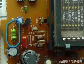
Inductor on the board
The inductor coil is made by winding the insulated wire around the insulated bobbin by a certain number of turns.
DC can pass through the coil. The DC resistance is the resistance of the wire itself. The voltage drop is very small. When the AC signal passes through the coil, the self-induced electromotive force will be generated at both ends of the coil. The direction of the self-induced electromotive force is opposite to the applied voltage, which hinders the AC. Pass, so the characteristic of the inductor is DC resistance AC, the higher the frequency, the greater the coil impedance. The inductor can form an oscillating circuit with the capacitor in the circuit.
Inductors generally have a straight-label method and a color-code method, and the color-code method is similar to a resistor. Such as: brown, black, gold, gold means 1uH (error 5%) of the inductance.
The basic unit of inductance is: Hen (H) The conversion unit is: 1H=103mH=106uH.
Five, crystal triode
The transistor is commonly represented by a "Q" plus a number in the circuit. For example, Q1 represents a triode numbered 1.
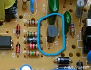
Transistor on the board
1. Features: A crystal triode (referred to as a triode) is a special device that contains two PN junctions and has amplification capability. It is divided into two types: NPN type and PNP type. These two types of triodes can complement each other in terms of working characteristics. The so-called tube in the OTL circuit is paired with PNP type and NPN type.
Commonly used PNP type triodes are: 9012, 9015 and other models; NPN type triodes are: 9011, 9012, 9013, 9014, 9018, and other models.
2. The crystal triode is mainly used for amplifying in the amplifying circuit.
The multi-stage amplifier intermediate stage is used, the low-frequency amplifying input stage, the output stage or the high-frequency or wide-band circuit and the constant current source circuit for impedance matching.
3. Identification of crystal triode
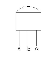
Figure 1-2
Commonly used crystal triodes are packaged in two types: metal package and plastic package. The arrangement of the pins has a certain regularity. For low-power metal package triodes, place them in the bottom view position so that the three pins form the apex of the isosceles triangle upwards, from left to right, e, b, c; for medium and small power plastic package triodes, according to the figure Show 1-2 position with its plane facing itself and three pins facing down, then e, b, c from left to right.
Liquid Crystal Display For Vehicle Use
Dongguan Yijia Optoelectronics Co., Ltd. , https://www.everbestlcdlcm.com
