The tube has a knee voltage. In the output characteristic curve (Figure 1-3), after the load becomes larger, the intersection between the load line and the leftmost side of the output characteristic curve will become smaller, and the knee voltage will move to the left, so that the voltage swing can become larger (otherwise, the same It will be overvoltage under input). The probability that the signal is distributed in the vicinity of the mean value is not large, and the probability of the occurrence of signals that are too large and too small is relatively small.
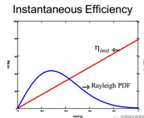
In today's world, the development of communication technology can be described as changing with each passing day (to be precise, human desires are changing with each passing day ...). However, the current wireless communication that humans rely on is entirely through radio, and the frequency bands are mostly concentrated below the C band, which is quite crowded. Then, in order to increase the amount of information transmission within the limited spectrum resources, the signal modulation method is becoming more and more complex, and many non-constant envelope modulation methods such as 64QAM and 256QAM have appeared, so that the peak-to-average ratio of the signal is constantly Become bigger. Figure 1-1 is a comparison diagram of the instantaneous probability distribution of the signal envelope and the instantaneous efficiency curve of the class AB power amplifier (why is it compared with the class AB? Because the base station power amplifier was of this type not too long ago).

Figure 1-1 Envelope efficiency and envelope probability distribution of class AB amplifier
It is not difficult to see that the probability that the signal is distributed around the small and large mean is large, and the probability of the occurrence of signals that are too large and too small is relatively small. However, it can also be seen from the figure that the efficiency of the AB power amplifier increases with the increase of the signal power, so the efficiency of the power amplifier is very low near the average. When the base station power amplifier adopts the class AB power amplifier, it is often necessary to work back from P-1dB to about 6dB. The efficiency at this time will be reduced from 50% to 20% (for example, not the data), do n’t underestimate, if The rated output power is required to be 100W, and you can calculate how much power is going to heat up. . Therefore, the traditional class AB amplifier cannot meet the requirements of modern communication systems for the efficiency of the amplifier. Therefore, it is necessary to design a high-efficiency power amplifier to meet the efficiency requirements of the system. Maybe you will say that this is difficult. Switching power amplifiers (such as class E) and harmonic control power amplifiers (such as class F) have a theoretical efficiency of 100%. But unfortunately, the linear correction of these high-efficiency amplifiers is very difficult, and it directly kills the DPD (the algorithm must be cheered ...), and the working bandwidth of these high-efficiency amplifiers is not enough, and the reliability is not it is good. Fortunately, there is no other way. Fortunately, as early as 1936, Mr. WH Doherty invented the Doherty power amplifier architecture. The power amplifier of this architecture can have higher efficiency and better linearity at the same time when the power amplifier returns to work. What is the principle of such awesome power amplifier architecture, the following step by step to deconstruct the Doherty power amplifier architecture (the following explanation is for students who understand the working principle of the power amplifier tube, students who do not know the working principle of the power amplifier, please stop, make up for the basic knowledge first...).
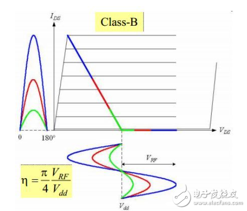
Load traction principleBefore explaining the working principle of Doherty, we must first talk about its lifeblood --- load traction. So what is load traction? We all know that the power amplifier will have a static working point and load line when working. Take the power amplifier tube biased in class B as an example, its intention under a fixed load is shown in Figure 1-2.

Figure 1-2 Schematic diagram of fixed load
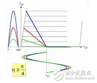
It can be seen from the figure that the drain current is a cosine pulse, which means that the power amplifier has no overvoltage and works in an undervoltage state. This premise is very important, because in the efficiency calculation at this time, the ratio of fundamental current to DC current It has been determined by the bias. The efficiency of the power amplifier is proportional to the drain RF voltage swing (the specific explanation is written in a large article, and the code is free when available). Therefore, in order to obtain high efficiency, the power amplifier should be in a voltage saturation state, that is, the RF voltage swing should be close to the drain power supply voltage. Several different colored signals in the figure represent different input and output power. It can be seen that the lower the output power, the lower the efficiency (smaller voltage swing). However, our demand is to obtain high power amplifier efficiency in the mean area of ​​the input signal, that is to say, when the input signal is small, the voltage swing can also be close to the drain supply voltage. This cannot be done with fixed bias and load impedance. So if the bias state is required to be unchanged, what should we do to achieve high efficiency? You may have found that the smart way to achieve this goal is to make the load of the power amplifier larger, let the power amplifier reach a voltage saturation at a smaller output power level, and obtain high efficiency. This is called load modulation. Figure 1-4 is a schematic diagram of load modulation.

Figure 1-3 Schematic diagram of load modulation
It can be seen from the figure that as the load continues to increase (from blue to green), the drain voltage swing of the amplifier becomes closer to the drain power supply voltage, and the efficiency of the amplifier becomes higher and higher. By selecting the appropriate load impedance, the power amplifier can have high efficiency when outputting the average power.
I will say so much this time. I did not mention the premise of some expressions, such as the harmonic short-circuit conditions of the power amplifier, etc. The purpose is to make the load modulation clear first. Other issues and improper expression of knowledge, please discuss. The next time talk about the specific working process of the classic two-way symmetric Doherty.
Cylindrical lenses are only used to provide focusing ability in one part. Used to illuminate or detect light from a linear light source. It is also used for deformation and compression of beams and images. Especially widely used in LD (laser diode) output beam deformation compression. Cylindrical lenses and components are used in a wide range of industries. Some industrial sectors that often use cylindrical lenses are: industrial inspections. Examples include laser scanning optical metrology systems, laser alignment and inspection tools, and laser additive manufacturing and laser processing equipment. Semiconductor manufacturing. In the entertainment industry, cylindrical optical components are used in digital cinema cameras to compress widescreen images, making them suitable for standard 35mm film and digital/laser projectors to stretch and compress images so that they can be viewed normally when projected onto a widescreen. In life sciences and medicine, cylindrical lenses are used in various life science imaging and medical testing instruments.
Cylindrical Lens,Plano Convex Cylindrical Lens,Plano Concave Cylindrical Lens,Cylinder Lens
Zoolied Inc. , https://www.zoolied.com
