A design of a digital micromirror device (DMD) driving waveform experimental platform based on ARM and FPGA is proposed. The design consists of a digital micromirror driver and a voltage converter. The hardware working principle of digital micromirror driver and voltage converter is described, as well as the software workflow of ARM microcontroller and FPGA. Experimental results show that the system can meet the expected design requirements.
The digital micromirror device DMD (Digital Micromirror Device) was invented by Texas Instruments in 1987 [1], and its imaging system has the advantages of small size, light weight, rich image color and high definition. The application is very extensive, and has been extended from the field of initial projection and high-definition digital television to stereoscopic display and graphic printing [2]. Compared with foreign leading technologies, China's research in this area is relatively lagging behind, so the research on digital micromirrors and their driving technologies is of great significance. In the development of the driver of digital micromirror devices, an important process is to find the optimal driving waveform and optimal driving voltage to control the micromirror flip. Due to the different micro-mirror manufacturing processes and different physical properties, different products require different driving waveforms to meet their driving requirements. In the current research and development, there is a lack of a universal driving waveform experimental platform, and the design proposed in this paper meets the needs of this aspect.
1 DMD drive principle and its driving factors1.1 DMD drive principle
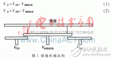
Digital micromirror devices are based on semiconductor manufacturing technology and consist of a high-speed digital light-reflecting switch array [3]. A digital light reflection switch is referred to as a micromirror unit. In the rendering process, each micromirror unit corresponds to one pixel in the image, and the rendered image and its characteristics are changed by controlling the rotation angle and time of the micromirror. Figure 1 shows the mechanical structure of a micromirror unit. The micromirror has three microelectrodes, namely: VON, VMIRROR, VOFF, where VMIRROR is the bias voltage, and VON and VOFF are the driving voltages. The three microelectrodes can be activated by digital signals. The level of the micromirror switches can be controlled by equations (1) and (2):

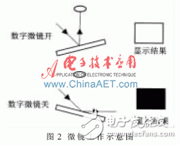
When V is high and V is low, the lens is facing the light source (on), and a white pixel will be reflected to the screen through the lens; when V is low and V is high The lens avoids the light source (off) and the mirror pixel appears dark on the screen. It is realized that the flip direction of the micromirror unit is adjusted by the digital signal, thereby changing the image. In order to produce an image with varying gray levels, it is necessary to control the timing of the state of the micromirror switch. By controlling the duration of the high level, that is, changing the duty cycle of the driving waveform: when the V open remains high for a long time, the micro mirror turn-on time is also long, and the corresponding gray pixel is shallow; V is kept high. When the flat time is long, the micromirror off time is also long, and the corresponding grayscale pixels are deep. The micro-mirror working diagram is shown in Figure 2.

1.2 DMD driving factors
In the DMD chip, the micromirror is the smallest unit of work and the key to its performance. DMD is a member of MEMS MEMS, which controls the deflection of micromirrors by the action of electrostatic force [4]. Therefore, the performance of micromirrors is closely related to its manufacturing process. In the process of micromirror inversion, the micromirror is finally stabilized at the corresponding position under the action of the mechanical structure limit and the control voltage [5], so the mechanical structure and the control voltage need to be perfectly matched to ensure the perfect operation of the micromirror. .
Through the above analysis, it can be seen that different manufacturing processes and different micro-mirror mechanical structures put different requirements on the driving waveform of the digital micro-mirror device. For different micromirrors, the corresponding optimal working mode is also different, and it is necessary to find the best driving waveform mode in the driver development process.
2 system functions and overall plan2.1 System function
The system consists of a digital micromirror driver and a voltage converter to realize the setting, generation and adjustment of the driving waveform. The advantages are as follows: (1) the flexibility of the system is enhanced, and other functions are easily extended; (2) the operation is simple and convenient, and the controllability is strong. The whole system has strong variability. For different digital micro-mirror devices, the driving waveform can be easily set, the driving voltage can be adjusted, and the optimal working state can be determined. The voltage amplitude range can reach 10 V~60 V.
2.2 Overall plan
The overall design of the system is divided into two parts: a digital micromirror driver and a voltage converter. The digital micromirror driver mainly completes the parameter setting of the receiving PC, generates waveforms, and adjusts waveforms, wherein communication with the PC is done based on USB. The voltage converter mainly performs the conversion of the driving voltage and the collection and amplification of the load current.
3 hardware circuit design and implementation3.1 Hardware system of digital micromirror driver
The digital micromirror driver is the core part of the driving waveform experimental platform. The hardware system is shown in Figure 3. The system combines ARM microprocessor (S3C2440) and FPGA. As the control core, ARM microprocessor mainly realizes the following functions: (1) Communicate with PC to realize editing and input of parameters related to driving waveform of digital micro-mirror device; (2) Communicate with FPGA to transmit relevant parameters of target driving waveform and Control command; (3) control light source controller (color wheel, LED, Laser); (4) control touch screen for menu display, status display and simple control and setting; (5) process current feedback information, and adjust in time Drive the waveform. The system makes full use of the rich external interface of ARM microprocessor, including touch screen, USB interface, etc., which improves the practicability of the system and makes the operation more humanized.
Vozol Cora Mini Vape are so convenient, portable, and small volume, you just need to take them
out of your pocket and take a puff, feel the cloud of smoke, and the fragrance of fruit surrounding you. It's so great.
We are China leading manufacturer and supplier of Disposable Vapes puff bars, vozol cora mini bar vape,vozol cora mini disposable vape,
vozol cora mini e-ciagrette, and e-cigarette kit, and we specialize in disposable vapes, e-cigarette vape pens, e-cigarette kits, etc.
vozol cora mini bar vape,vozol cora mini disposable vape,vozol cora mini e-ciagrette,vozol cora mini vape pen,vozol cora mini refilled vape
Ningbo Autrends International Trade Co.,Ltd. , https://www.mosvape.com
