The time delay relay is a kind of relay that uses the pulse delay principle to realize the delay on-off function. It is often used in relay protection and automation circuits as a time component for delay return after AC instantaneous power failure.
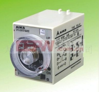
First, the working principle of time delay relay - classification
Common time delay relays are airbag and electronic, as well as clock type:
1. The airbag type time delay relay delays the execution of the command by deflation of the gas in the airbag through the small hole after starting with the electromagnet.
2. The electronic time delay relay is delayed by the electronic circuit to execute the command.
3, the watch type time delay relay, using the escapement of the clock to control the release time of a similar spring spring, high precision.
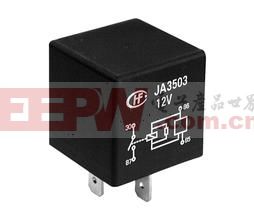
Second, the working principle of time delay relay - circuit diagram
1, transistor relay delay circuit diagram:
Figure 1 is a relay delay pull-in circuit composed of transistors. When the power is first turned on, the voltage on the 16μF capacitor is zero, both transistors are turned off, and the relay does not operate. With the charging of the 16μF capacitor, after a period of time, the voltage on it reaches a high level, both transistors are turned on, and the relay delays the pull-in. The delay time can reach 60s. The length of the delay can be adjusted with a 10MΩ resistor.
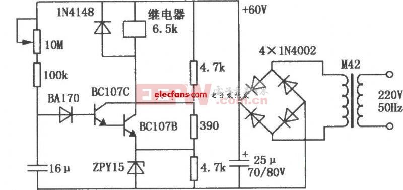
Figure 1 Relay delay circuit for transistor
2. Power-on delay relay circuit:
This circuit takes advantage of the base breakdown voltage of the emitter/an ordinary bipolar transistor. A 2N3904 transistor at the emitter/base junction of the reverse connection acts as an 8 volt Zener diode which creates a higher turn-on connection to the Darlington transistor pair voltage. Almost all bipolar transistors can be used, but the Zener voltage will likely be about 6 to 9 volts for a particular transistor used. The time is approximately 7 seconds delay using a 47K resistor and a capacitor of 100uF, which can be reduced by reducing the R or C value. A longer delay can get a larger capacitor, and the time of the resistor should not increase by 47K. The circuit should work with any 12 volt DC relay, with a 75 ohm resistor or multiple coils. The 10K resistor provides a power-off when the entire supply connection is not needed, and if the power supply already has a bleeder resistor, the capacitor discharges the path.
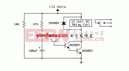
Figure 2 power-on delay relay circuit
Third, the working principle of time delay relay - graphic symbol

Figure 3 graphical symbol of the power-on delay relay
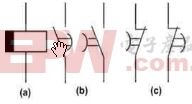
Figure 4 graphical symbol of the power failure delay relay
Fourth, the working principle of the time delay relay - power failure delay, power delay, delay intermediate
When the rated point voltage is applied, the internal relay of the time delay relay and the two time delay relays instantaneously operate, the electric shock is switched, and the power supply circuit and the timing circuit are in a de-energized state, so as to improve the anti-interference performance of the relay, when the input voltage is greatly reduced or When it disappears completely, the momentary relay returns instantaneously (the two delay execution relays are still in the operating state), and the contacts also return instantaneously, so that the energy storage power supply is turned on in the timing loop, the crystal oscillation generates a clock pulse, and the frequency is divided to obtain 10ms timing. Pulse, the counter counts the timing pulse. When the counted pulse number matches the setting switch value, the drive execution relay returns to complete the function of delay return after power failure.
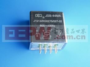
1, power off delay
(1) Introduction: The power-off delay relay is used for relay protection and automation of AC operation, as the time component of delay return after instantaneous (DC) power-off after instantaneous power-off.
(2) Technical requirements:
1), delay range: 0.02-5.00S, grade difference 0.01S; 0-999S, grade difference 1S;
2), action value: the operating voltage DC should not be greater than the rated voltage of 70%, the AC should not be greater than the rated voltage of 80%;
3), contact capacity: in the voltage does not exceed 250V, the current does not exceed 1A, the time constant is 5MS ± 0.75MS DC in the sense load circuit, the contact breaking capacity is not less than 50W; the voltage does not exceed 250V, the current does not exceed 5A, in an AC circuit with a power factor of COSφ=0.4±0.1, the disconnection capacity is not less than 500 VA. The contact can reliably operate and return no less than 50,000 times under the above specified load conditions. The contact allows the on-current to be no less than 5A for a long time.
4) Power consumption: no more than 5W/7VA under rated value.
5), insulation performance: the same voltage between the opening point is not less than 1KV / 50Hz for 1 minute of the power frequency withstand voltage. Between different sets of contacts, the power frequency withstand voltage of 1KV/50Hz is not less than 2 minutes between different circuits. Test any terminal-to-case with a 1KV shaker with an insulation resistance of not less than 100M.
2, power-on delay
(1) Introduction: The power-on delay time relay is used in the secondary circuit relay protection and automatic control loop of the power system. As a delay device, the controlled component gets the required delay; the delay range is 0.02-9.99S, 0.02-99.99S, 0.02S-999H; This relay is a rail type integrated circuit static type relay with high precision, low power consumption, accurate operation time, intuitive and convenient setting, wide range, completely replaceable electromagnetic type time relay, large volume Time relay used in the complete switchgear.
(2) Technical requirements:
1), delay accuracy
A. The average error of the delay setting value; under the reference condition, the absolute value of the relay delay setting average error is not more than 0.1% +3ms of the setting value; the average error = (5 times the average value - setting value) / setting value *100%
B. Delay consistency: Under the reference condition, the relay delay consistency is not greater than the setting value (3-10ms)
C. At the temperature of -10~50°C, the absolute value of the average error (including consistency) of any delay setting value is not more than 0.1%+5ms of the setting value.
2) Working voltage: When the operating voltage is not more than 70% of the rated voltage, the relay should work reliably.
3), the return time of the relay
The time to cut off the electrical power supply and return the outlet contact to the starting position should be no more than 25ms for the type of work using the DC power supply.
4) When the return voltage of the relay is reduced and the relay voltage is not less than 10% of the rated voltage, the relay contacts should return reliably.
5), power consumption is not more than 2.5w (4.5VA)
3, the middle of the delay
(1) Introduction: The time delay intermediate relay is used in various protection and automatic control lines for DC or AC operation as an auxiliary relay to increase the number of contacts and contact capacity. The power-on delay or power-off delay can be adjusted as needed.
(2) Technical parameters:
1), environmental reference conditions: ambient temperature: 20 ± 2 ° C; relative humidity: 45% ~ 75%; atmospheric pressure: 86 ~ 106 Kpa
2), normal use conditions: ambient temperature: -10 ° C ~ +50 ° C; ambient relative humidity: not more than 90%; atmospheric pressure: 86 ~ 110Kpa; limit temperature during storage and transportation: -25 ° C ~ +70 ° C; The altitude of the place of use: no more than 2,500 meters; the surrounding medium of the use environment is not explosive and does not contain corrosive gases; the concentration of conductive dust contained should not lower the insulation level below the allowable limit.
3), the maximum power consumption: no more than 7VA under the rated voltage of 380VAC; no more than 4VA under the rated voltage of 220VAC.
4), characteristic parameters: operating range: 0.04 ~ 1S level difference: 0.01S error is not more than 3ms; 0.1 ~ 10S level difference: 0.1S error is not more than 3ms; power supply voltage: 220VAC, 380VAC, 110VDC, 220VDC
5), the allowable fluctuation range of the power supply: 0.8 ~ 1.15 times the rated voltage.
6), contact maximum capacity: cut off load capacity: DC 250V or less, Ï„ = 5ms, inductive load 50W, resistive load 150W; AC 250V or less, load 1200VA; allow long-term switching current: 5A.
7) Insulation resistance: The insulation resistance between each lead terminal and the terminal rail is measured by a 1000V shaker to be not less than 10MΩ.
8) Insulation withstand voltage: Each lead terminal can withstand the power frequency voltage of 2000V for the terminal guide rail, and can withstand the power frequency voltage of 1000V between the same group of contacts, and has no breakdown for one minute.
9) Electrical life: The contact is 10,000 times under rated load.
10) Mechanical life: The contact is 3 million times under no-load condition.
Simply put, the power-on delay is when the coil is energized, the delay contact is delayed, and the coil is immediately reset after being powered off;
The power-off delay is that the coil is energized, the delay contact will work immediately without delay, and the coil will be delayed immediately after the power is cut off;
Delayed contacts are time-delayed and time-delayed contacts.
Capacitor
Remote Monitor Systems Battery
Remote Monitor Systems Battery,E Cigarette Lithium Battery,Semi Tight Lithium Battery,Intelligent Oem Lithium Battery
Jiangmen Hongli Energy Co.ltd , https://www.honglienergy.com
