The driving source of the industrial robot drives the movement or rotation of the joint through the transmission member, thereby realizing the movement of the body, the arm and the wrist. Therefore, the transmission components are important components that constitute an industrial robot. According to the type of transmission, the transmission components can be divided into two categories: linear transmission and rotary transmission.
First, linear transmission mechanismThe linear transmission mechanism commonly used in industrial robots can be directly generated by cylinders or hydraulic cylinders and pistons, or can be converted from rotational motion by transmission components such as rack and pinion and ball screw nut.
1. Moving joint rails
Moving the joint rail during the movement can play a role in ensuring positional accuracy and guidance. There are five types of moving joint rails: ordinary sliding guides, hydraulic dynamic sliding guides, hydrostatic sliding guides, air bearing rails and rolling guides.
The first two kinds of guide rails have the advantages of simple structure and low cost, but it must have a gap for lubrication, and the magnitude and direction of the robot load change rapidly, and the existence of the gap will cause changes in the coordinate position and changes in the payload; In addition, the friction coefficient of such a guide rail changes with the change of the speed, and the creep phenomenon is likely to occur at a low speed.
The third static-pressure rail structure can produce a preload, completely eliminate the gap, and has the advantages of high rigidity, low friction, high damping, etc., but it requires a separate hydraulic system and a mechanism for recovering lubricating oil.
A disadvantage of the fourth air bearing rail is that the stiffness and damping are low.
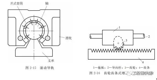
At present, the fifth type of rolling guide is the most widely used in industrial robots. The structure of the inclusive rolling guide is shown in Figure 2-15. It is supported by the support base and can be easily connected to any plane. In this case, the sleeve must be open. Embedded in the ram, it increases stiffness and facilitates connection to other components.
2. Rack and pinion device
In the rack and pinion device (Fig. 2-16), if the rack is fixed, when the gear rotates, the gear shaft moves along with the carriage in the direction of the rack. Thus, the rotational motion of the gear is converted into a linear motion of the carriage. The carriage is supported by a guide or rail, and the device has a large backlash.
3. Ball screw and nut
Ball screws are often used in industrial robots because the ball screws have low friction and fast motion response.
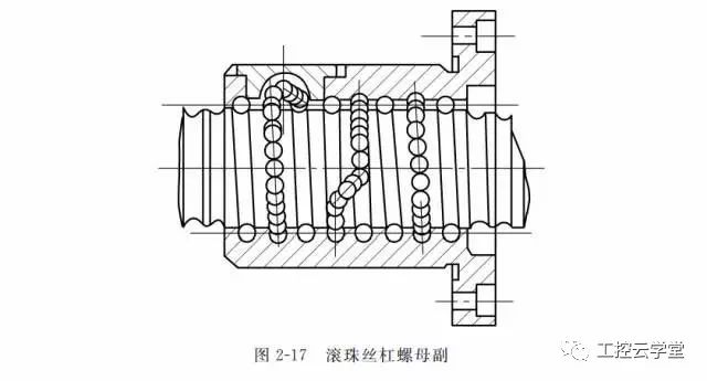
Since many balls are placed in the spiral groove of the ball screw nut, the screw is subjected to rolling friction during the transmission process, and the friction is small, so the transmission efficiency is high, and the creep phenomenon during low-speed movement can be eliminated; When a certain preload is applied, the backlash can be eliminated.
As shown in Figure 2-17, the balls in the ball screw nut are reciprocated to transmit motion and power through the ground guide groove. Ball screw transmission efficiency can reach 90%
4. Liquid (gas) pressure cylinder
The liquid (gas) pressure cylinder is an actuator that converts the pressure energy output from the hydraulic pump (air compressor) into mechanical energy and performs linear reciprocating motion. The liquid (gas) cylinder can easily realize linear motion. The liquid (gas) pressure cylinder is mainly composed of a cylinder tube, a cylinder head, a piston, a piston rod and a sealing device. The piston and the cylinder tube are precision sliding fit, and the pressure oil (compressed air) enters from one end of the liquid (gas) pressure cylinder. , push the piston to the other end of the liquid (gas) pressure cylinder to achieve linear motion. The direction and flow of the liquid (gas) cylinder can be controlled by adjusting the flow direction and flow rate of the hydraulic fluid (compressed air) entering the liquid (gas) cylinder.
Second, the rotating transmission mechanismGenerally, the motor can directly generate rotary motion, but its output torque is smaller than the required torque, and the rotational speed is higher than the required rotational speed. Therefore, it is necessary to use a gear, a belt conveyor or other motion transmission mechanism to convert the higher rotational speed into a lower speed. The speed and the larger torque. The transfer and conversion of motion must be done efficiently. And it can not detract from the characteristics required by the robot system, including positioning accuracy, repeat positioning accuracy and reliability. The transmission and conversion of motion can be achieved by the following transmission mechanisms.
Gear pair
The gear pair can not only transmit the angular displacement and angular velocity, but also transmit the force and torque. As shown in Figure 2-18, one gear is mounted on the input shaft and the other gear is mounted on the output shaft to obtain the number of teeth and its speed. In inverse proportion [Equation (2-1)], the ratio of the output torque to the input torque is equal to the ratio of the number of output teeth to the number of input teeth [Equation (2-2)].

2. Timing belt drive
In industrial robots, the timing belt drive is mainly used to transmit motion between parallel axes. The contact faces of the synchronous conveyor belt and the pulley are made into corresponding tooth shapes, and the power is transmitted by the meshing. The transmission principle is shown in Figure 2-19. The pitch of the teeth is indicated by the circular pitch t when the enveloping pulley is used.
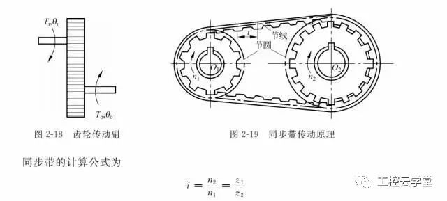
Where: n1 is the driving wheel speed (r/min); n2 is the passive wheel speed (r/min); z1 is the number of driving gear teeth; z2 is the number of passive gear teeth.
Advantages of timing belt transmission: no sliding when driving, accurate transmission ratio, stable transmission; large speed ratio range; small initial tension; shaft and bearing are not easy to overload. However, such a transmission mechanism requires strict manufacturing and installation, and the material requirements for the belt are also high, so that the cost is high. The timing belt drive is suitable for transmission between the motor and the high reduction ratio reducer.
3. Harmonic gear
At present, 60%~70% of the rotating joints of industrial robots use harmonic gear transmission.
Harmonic gear transmission consists of three main parts: rigid gear, harmonic generator and flexible gear, as shown in Figure 2-20.
In operation, the rigid gear 6 is fixedly mounted, each tooth is evenly distributed on the circumference, and the flexible gear 5 having the outer ring gear 2 is rotated along the inner ring gear 3 of the rigid gear. The flexible gear has two teeth less than the rigid gear, so the flexible gear reverses the corresponding rotation angle of the two teeth every revolution of the rigid gear. The harmonic generator 4 has an elliptical profile, the balls mounted thereon are used to support the flexible gear, and the harmonic generator drives the flexible gear to rotate and plastically deform. When rotating, only a few teeth of the flexible end of the flexible gear mesh with the rigid gear, so that the flexible gear can freely rotate through a certain angle with respect to the rigid gear. Usually the rigid gear is fixed, the harmonic generator is used as the input, and the flexible gear is connected to the output shaft.
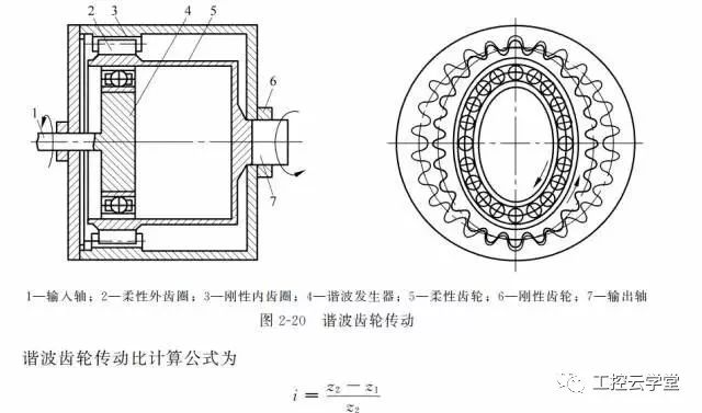
Where: z1 is the number of teeth of the flexible gear; z2 is the number of teeth of the rigid gear. Assuming that the rigid gear has 100 teeth and the flexible gear has two teeth less than it, when the harmonic generator turns 50 turns, the flexible gear rotates one turn, so that only a small space is required to obtain a 1:50 reduction ratio. . The harmonic generator is usually mounted on the input shaft and the flexible gear is mounted on the output shaft to obtain a larger gear reduction ratio.
4. Cycloidal pinion drive reducer
The cycloidal pinwheel drive is a new type of transmission developed on the basis of the pinion drive. In the 1980s, Japan developed the cycloidal pinion drive reducer for robot joints. Figure 2-21 shows the pendulum. Line pin wheel drive diagram,
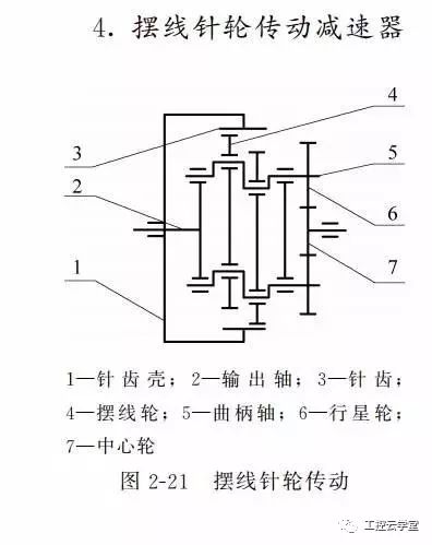
It consists of an involute cylindrical gear planetary reduction mechanism and a cycloidal pinion planetary reduction mechanism. The involute planetary gear 6 is integrated with the crankshaft 5 as an input to the cycloidal pinion transmission portion. If the involute center wheel 7 rotates clockwise, the involute planetary gear rotates counterclockwise while revolving, and drives the cycloidal wheel through the crankshaft for planar motion. At this time, the cycloidal wheel is revolved in the opposite direction, that is, clockwise, due to the constraint of the pin wheel engaged with it, while its axis revolves around the axis of the pin wheel. At the same time, it pushes the planet carrier output mechanism clockwise through the crankshaft.
27 Inch Aio,All In One Pc 27 Inch,All In One Desktop Touch Screen,All In One Pc Touch Screen
Guangzhou Bolei Electronic Technology Co., Ltd. , https://www.nzpal.com
