
The KT88, which has been popular in recent years, has a large output power, but the sense of hearing seems to be unsatisfactory. It seems that the sound is loud and the sound has no advantage. This phenomenon indicates that the sound pressure frequency characteristics are poorly balanced, the in-ear sensitive midrange area is too large in comparison with the high and low sound areas, and the second is that the sound pressure has poor detail performance. Therefore, if the direct heat pipe drive is used, there will be a significant improvement. 4PIS uses RC coupling voltage amplification circuit. Driving the push-pull output stage is bound to add an inverter circuit. At the same time, the resistive load also limits the dynamic range of the 4PIS, affecting the output stage. In this paper, 4PIS power amplification state is adopted, and the optimal load matching is realized by driving the transformer, and the low distortion and large driving signal are obtained on the optimal load resistance. At the same time, the inverter function is completed by the drive transformer with the ratio of I:I+l, and the A.ABI type high power output stage is driven.
The same as a small power tube as a driver stage, the voltage amplification and power amplification modes have completely different concepts. A. The AB1 class output stage requires no power drive, but the drive stage is in the power output state with the best matching load impedance, which can take advantage of large dynamics and low distortion. The design of the power tube voltage amplification state is focused on obtaining a high-amplitude voltage output, so it is inevitable to use a large load resistor (or a large-inductance choke, a drive transformer). In the case of any power tube in this impedance mismatch, it is almost impossible to input a high voltage. In fact, the dynamic linear region is extremely small and the nonlinear distortion is also increased. A power amplifier operating in an impedance matching state constitutes a driver stage, and the optimum load impedance is low (generally, the class A single terminal rarely exceeds 50000. In this example, the 4PIS is only 3000 Ω). To ensure that there is enough linear working area. What follows is the low load impedance, so that the primary inductance of the drive transformer does not need to be large enough to meet the low frequency extension of Hi~Fi playback. Therefore, the winding process for driving the transformer is simplified. In the past, the voltage amplification mode drives the primary inductance of the transformer to be usually between 50H and 150H, and is wound into 1:1. The total number of turns is staggering, and the excessive number of turns increases the distributed capacitance, and the "big public" is intensified.
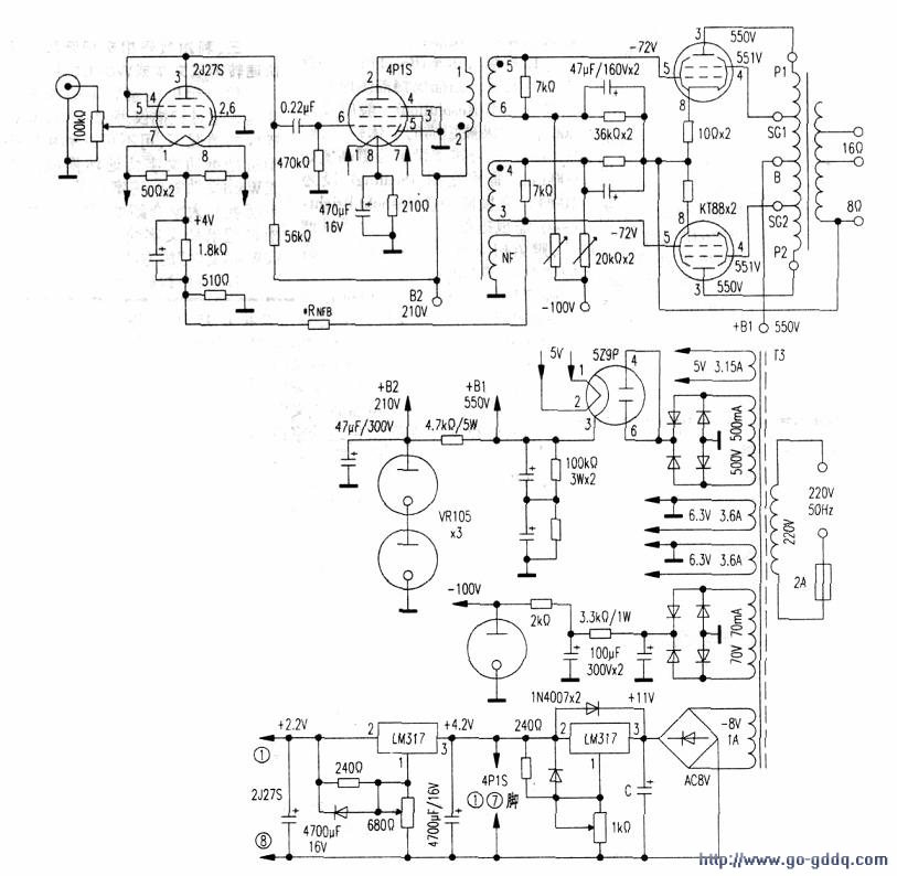
The figure is a 4PIS power state driven 2xKT88 ultra linear 50w post amplifier circuit. The amplifier circuits at each level have the following characteristics:
First, the output level features 2xKT88 output level according to the British KT88 developer GE company to provide circuit data, working in super linear amplification state, the basic data is as follows:
Plate + G2 voltage 550v. Current static value 2x50mA; gate negative voltage -72V; static board consumption (27.5W per tube), load impedance (plate-plate) 4.5kΩ; second gate tap ratio 40%, second gate negative feedback amount -9dB The KT88UL state has an internal resistance of 1.52kΩ. In the above state, when the grid. When the gate input signal is 2x70Vp-p, the output power is IOOW. THD is about 2%. When the input signal is 2x52Vp-p, the output power is 52W, and the plate current peak is 198mA. THDl.5% or less.
In this example, the second driving state is adopted, and the DC operating point is the same as that of the former. Since the input signal is reduced to 2x52Vp-p, the peak value of the maximum signal current is 198mA. The output power is reduced to 52W, and the linearity in the work area is greatly improved.
Since the DC operating point is constant, it is only necessary to increase the input signal amplitude to 2x70Vp-p to obtain 100W output power, but the THD is slightly increased.
Second, 4PIS driver level parameters
This machine design output 50w. Therefore, the final stage drive signal is only 50Vp-p two sets of anti-phase signals. The 4PIS driver stage operates in a five-pole connection class A power amplification state. The data is as follows:
The plate voltage is 210V; the second gate voltage is 210V; the total cathode current (Ia+lg2) is 32+6.5mA, and the gate negative voltage is -8v. Self-supplied gate negative voltage resistor Rk'-SW38.5mA=208Ω. Use a nominal value of 210Ω1W resistor. When inputting 7Vp-p signal, the output power is about 1.5W. At the optimal load end of 3500Ω, the output voltage is Uo=1, 5Wx3500Ω, the square root value is 72.5Vrms, and the peak value is IOIVp-p. In order to get two sets of anti-phase drive signals. 4PIS uses the drive transformer output, the primary and secondary turns ratio is I:I+I. A 7kΩ resistor is connected to each of the two sets of secondary, and the impedance to the primary is 3.5kΩ. At the same time, two sets of driving outputs with the opposite phase and the primary voltage are obtained on two stages.
Third, the first stage and negative feedback design front stage still uses 2127S three-pole connection RC coupling amplifier. 2J27S uses 210V power supply, load resistance Ra=56Ω, and the same circuit as above, its open loop gain is about 14 times or less, and 4PIS driver stage voltage gain is about 14 times (output 101V, input 7V value). Then the total gain of the pre-stage circuit reaches 196 times, which means that the final stage wants to get the 50Vp-p drive signal. The amplifier input sensitivity should be 50V/196=255mVp-p. As a pure final stage power amplifier gain is obviously too high. The general input sensitivity is based on 500mV~lVp-p to reduce the front-level noise and avoid large signal distortion. If calculated by 800mV, the front stage has 60 times gain. This extra +10dB gain can add -lOdB negative feedback between the pre-stage and the driver stage to balance the gain of the whole machine and improve the front 4PIS. High internal resistance characteristics and nonlinear distortion of the pentode. At this point, the front and rear stages of the machine adopt independent negative feedback; the output stage is a 9dB second gate negative feedback, and a 10dB series voltage loop feedback is added between the pre-stage and the driver stage, which greatly improves the overall characteristics. Independent and negative feedback of the front and rear stages, the feedback amount of each channel is small, the amplification stage is small, and the phase shift is small, which makes the amplifier more stable.
Fourth, the characteristics of the power supply circuit The power supply has two sets of high-voltage output, the first group is 550v. Power is supplied to the UL output stage, and the full-wave vacuum rectifier 529P is used as a high voltage delay. To meet the requirements of KT88. The high voltage is output after about 45 seconds after starting up to protect the KT88 cathode from damage. At the same time, the high pressure delay tube has a certain internal resistance. And the filter capacitor constitutes RC filter to help reduce ripple and reduce the peak capacitance of the filter capacitor. When using a two-channel structure. The maximum current of 198 mA per channel is sufficient for 529P. If it is mono, you can also use the domestic TV damper tube 6218P, 6219P. However, the filament needs to be changed to 6.3V.
The high-voltage 210V power supply of the front stage requires low ripple and high stability. Therefore, the 550v step-down filter is further connected to the stable 210V voltage by two inflating regulators VR105 (domestic WY-3P, Su-type cr3C) to ensure the safe use of 4PIS and 2J27S. The aerated voltage regulator tube is equivalent to a large capacitor, which makes the front power supply ripple lower.
The two tubes in the front stage are all direct heat type, in order to reduce the noise caused by the filament. The two sets of three-terminal adjustable voltage regulator ICLM317 are used to form a regulated power supply.
5. Two transformers must be made for production and adjustment. The output transformer T is designed to meet the requirements of GE for the primary impedance of 4200-4500Ω, and the rated output of the machine is 50w. Still designed according to the maximum output of 100W, in order to help reduce TZ loss and improve performance.
Input drive transformer Tl. No similar products are available for purchase, only self-winding as follows. TI is essentially a low-power Class A output transformer with high output impedance. Although the KT88x2ABl UL state gate has no gate current and does not consume driving power, Tl's matching resistor has power loss when the rated output voltage amplitude is 72Vrms per group. At approximately 0.7W per 7kΩ resistor. The signal power dissipation on the matching resistor actually also makes the output signal more stable.
Therefore, T2 needs to be designed according to the 3W~5W Class A output transformer.
E20 core is selected, the stack thickness is 22mm (large iron core section can improve the efficiency of the transformer). With a three-slot plastic skeleton, the intermediate groove is multi-layered with φ0.17mm enameled wire around 2000åŒ (the voltage is not high, it can be layered and flattened). The head is (2) and the tail is (1). Then use the φ0.12mm enameled wire to wrap around 2000åŒ on the other side of the groove, and the head is (6) and the end is (5). In the last side slot, the coil bobbin is removed, and the winding machine is mounted on the reverse body, using φ0.12mm line, and then winding another sub-2000åŒ, the head is (4) tail is (5), two sets of secondary one positive Winding (same as primary winding). Another set of rewinding purposes is to make the two ends of the two windings (4), (6) close to the core, and the induced voltage is reversed so that the two sets of outputs (3) and (5) The distribution parameters are completely symmetrical. The final NF winding can be φ0.21mm wire diameter, and the intermediate groove (primary outer side) is wound 95åŒ as a negative feedback winding, which corresponds to an impedance of 8Ω and a primary turns ratio of 2l:1. This winding can be adjusted without splitting and tailing during commissioning to achieve the phase requirement of negative feedback. The transformer core is inserted, and the two groups have a 0.2mm air gap to avoid magnetic saturation.
The B+ and C- voltages of this machine can be adjusted without automatic adjustment due to the voltage regulator tube. The only LM317 that needs to be adjusted to form a DC regulator can be used to set the output voltage with a dummy load method. 4.2V available 13Ω. The 1.4V uses a 28Ω resistor as a dummy load, and the 4.2V and 1.4V terminals are simultaneously connected to the corresponding load resistors, and the 4.2V is first set. Then set 1.4V.
Only the KT88 gate negative voltage needs to be adjusted in the amplifier. The T1(4) and (6) pins can be detected by the digital voltmeter, and the voltage value is coarsely adjusted to -72V. Then, on each of the two KT88 cathodes, the 1V DC voltmeter of each well was used to fine-tune the gate negative voltage resistance, so that the voltage drop across the two 10Ω resistors was the same, 0.5v, and the two tubes were statically balanced, each being 50mA. The more accurate this adjustment is, the better.
Fan Motor,Blower Motor,Condenser Fan,Condenser Fan Motor
Wentelon Micro-Motor Co.,Ltd. , https://www.wentelon.com