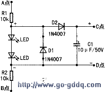
The method of replacing the battery with the caller ID: the LED in the figure is a common light-emitting diode, and the R1 and R2 are made of ordinary metal film resistors. After connecting the circuit as shown in the figure. Connect point A to the positive pole of the polarity switching bridge of the external line access point of the telephone, and point B to the negative pole of the polarity switching bridge. Connect point C to the positive pole of the battery clip of the phone, and point D to the negative pole of the battery clip.

Working principle: using the light-emitting diode conduction voltage of 1_8-2.0V, through R1, R2 current limit, from the external line voltage to obtain about 3.8V voltage, and then after D2, so that C and D between the two points at 3.2V. D1 is used to protect the LED from reverse breakdown. In addition to the 0.7V step-down, D2 also ensures that the battery does not discharge to the outside line. After all the connections are connected, the entire circuit is fixed in the excess space of the phone with a glue gun.
After the phone is installed with the above circuit, the battery is normally in a voltage hold state. The charging current is extremely small and the battery does not heat up. The battery only supplies power when the external line is powered off, keeping the information. After practical application, the phone is used normally for more than two years.
Shenzhen Ruidian Technology CO., Ltd , https://www.wisonen.com
