
First, the internal circuit circuit structure of the lower 555 is introduced as follows. Among them, the triode plays a control role, A1 is an inverting comparator, A2 is a non-inverting comparator, and the reference voltage of the comparator is divided by the power supply voltage +Vcc and the internal resistance. Decide. The RS flip-flop has a reset control function that controls the turn-on and turn-off of the transistor.
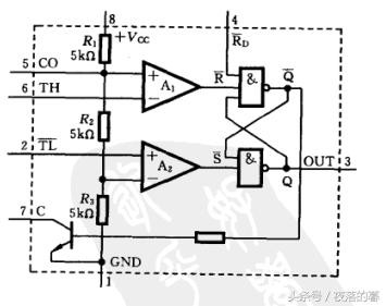
555 internal circuit
>>>>Touch Switch Circuit
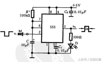
The 555 monostable trigger can be used as a touch switch. The circuit is as follows, where M is a touch metal piece or a wire. When there is no trigger pulse input, the output V0 of 555 is “0â€, and the light-emitting diode D is not lit. When the metal piece M is touched by hand. Corresponding to the input of a negative pulse on port 2, the internal comparator A2 of 555 is inverted, so that the output V0 becomes a high level "1", and the LED is lit until the voltage on the capacitor C is charged to Vc=2Vcc/3. The time when the diode is bright is Tp=1.1RC=1.1s. The circuit in the figure below can be used for touch alarm, touch timing, touch control, etc. The high and low levels of the circuit output signal are compatible with the digital logic level. In the figure, C1 is a high-frequency filter capacitor to keep the reference voltage of 2Vcc/3 stable, generally taking 0.01uF. C2 is used to filter the high-frequency interference introduced by the power supply current jump, generally taking 0.01uF ~ 0.1uF.
>>>> Frequency dividing circuit
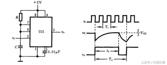
The monostable flip-flop consisting of 555 can form a frequency dividing circuit with a large splitting coefficient. As shown in the following figure, the input signal Vi is a column pulse train. After the first negative pulse triggers the 2 terminal, the output V0 becomes high level. Capacitor C starts to charge. If RC>>Ti, since Vc does not reach 2Vcc/3, V0 will remain high and T will be off. During this time, the input negative pulse does not work. When Vc reaches 2Vcc/3, the output V0 quickly goes low, the next negative pulse comes, the output jumps high again, and the capacitor C starts to charge, so it starts again.
Output pulse delay time tp=1.1RC Output pulse period T0=NTi
The division factor N is mainly determined by the delay time tp, and since the RC time constant can be made large, a large division factor can be obtained.
>>>>Two-stage timer
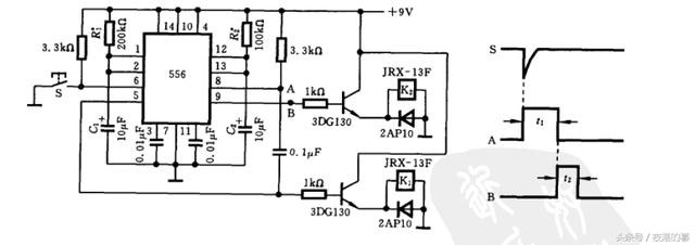
The following is a two-stage timer circuit consisting of a 556 (double 555). When the first stage timer is triggered by the switch S, a delay pulse is generated. The drive relay K1, A has a delay time t1 = ~1.1 R1xC 1
The negative transition generated at the end of the A pulse triggers the second stage timer, generating the delay pulse B, driving the delay time of the relay K2, B t2 = ~ 1.1R2xC2
In this way, each time the switch S is triggered, the start and reset of the relays K1 and K2 can be automatically completed, so the circuit can realize timing operation and control.
RandM Tornado 10000 is a Disposable Vape device with airflow control and it is rechargable. It contains 20ml 0/2/3/5% nicotine salt e-juice and vape up to 10000 puffs. There are 24 flavors for you to choose. The airflow control let you choose the best spot suit yourself plus it comes with a rechargeable Type-C port at the buttom of the device, which gurantte you finish the last drop of the ejuice in the tank all the time.
DISPOSABLE VAPE,Vape DEVICE WHOLESALE,vape device
Shenzhen Essenvape Technology Co., Ltd. , https://www.essenvape.com