
1 Introduction
In the bustling city, when the night falls, the colorful lights will light up, light up this dark world, add some fun to the people's life, and the water lamp is one of the roles. With the continuous development of technology, the circuit for controlling the lantern is constantly updated. Here, the flow lamp control circuit composed of 555 timer is mainly introduced.
2.555 timer
2.1 The internal structure of the 555 timer (as shown in Figure 1):
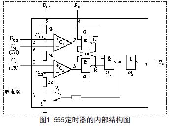
(1) Voltage divider
When the 15 feet are suspended.
When the 25-pin external control voltage is applied.
(2) Voltage comparator
Voltage comparators C1 and C2 are two ideal op amps of identical construction. The comparator has two inputs, with 1 and 0 respectively indicating the voltage applied to the corresponding input, using the comparison result representing the comparator (1 for high level and 0 for low level).
(3) Basic RS trigger
(4) Discharge transistor
V1 is an open collector discharge triode. At that time, V1 turned on; at that time, V1 was cut off.
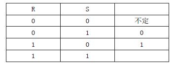
2.2 555 timer function table (as shown in Figure 2)
The 555 timer function table basically explains the function of the 555 timer.
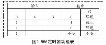
2.3 Multi-vibrator consisting of 555 timers
The multivibrator consisting of 555 timers is shown in Figure 3. RA, RB and C are external timing components. The high-level trigger terminal (6-pin) and the low-level trigger terminal (2-pin) are connected in the circuit. After connecting to the junction of RB and C, connect the discharge end (7 feet) to the junction of RA and RB. Because the capacitor C is too late to charge when the power is turned on, the voltage across the capacitor is low, less than (1/3) Vcc, so the high-level trigger and the low-level trigger are both low, and the output is high. Flat, discharge tube V1 is cut off. At this time, the power supply charges the capacitor C through RA, RB, so that the voltage rises exponentially. When it rises to (2/3) Vcc, the output is low, the discharge tube V1 is turned on, and the slave (1/3) Vcc rises to (2/3) Vcc. Because discharge tube V1 is turned on, capacitor C discharges through resistor RB and discharge tube, the circuit enters the second temporary steady state, and the length of its sustain time is related to the discharge time of the capacitor. The discharge, falling, when falling to (1/3) Vcc, the output is high, the discharge tube V1 is turned off, Vcc charges the capacitor C again, and the circuit is flipped again to the first temporary steady state.
Features
â—† Designed For Water and Dust Tight(IP67)
â—† Small Compact Sizeâ—† UL&ENEC&CQC Safety Approvals
â—† Long life & high reliability
â—† Variety of Levers
â—† Wide Range of wiring Terminals
â—† Wide used in Automotive Electronics,Appliance and Industrial Control etc.
â—† Customized Designs
Subminiature Dustproof Micro Switch
Micro Magnetic Switch,Micro Momentary Switch,Sealed Rotary Switch,Subminiature Dustproof Micro Switch
Ningbo Jialin Electronics Co.,Ltd , https://www.donghai-switch.com