Pull-up resistor experience summary
1. When the TTL circuit drives the COMS circuit, if the high level of the TTL circuit output is lower than the lowest level of the COMS circuit (generally 3.5V), then the pull-up resistor needs to be connected at the output end of the TTL to improve Output a high value.
2. The OC gate circuit must be connected with a pull-up resistor before it can be used.
3, in order to increase the drive capability of the output pin, some of the microcontroller pins often use pull-up resistors.
4. On the COMS chip, in order to prevent damage caused by static electricity, the unused pins cannot be suspended. Generally, the pull-up resistor is connected to reduce the input impedance and provide a discharge path.
5. The pin of the chip is added with a pull-up resistor to increase the output level, thereby improving the noise margin of the input signal of the chip and enhancing the anti-interference ability.
6. Improve the anti-electromagnetic interference capability of the bus. When the pins are suspended, it is easier to accept external electromagnetic interference.
7. The resistance mismatch in long-line transmission is easy to cause reflected wave interference, and the pull-down resistor is resistance matching, which effectively suppresses reflected wave interference.
Principle of selection of pull-up resistor values
From the perspective of the ability to sink current and save energy, it should have the characteristics of large resistance and small current. It should be large enough to save power and the current sinking capacity of the chip; the resistance is large and the current is small. From the perspective of ensuring sufficient drive current, it should be small enough; the resistance is small and the current is large. For high speed circuits, excessive pull-up resistors may flatten the edges.
Between 10K and 1K, it applies to the above three points. There is a similar reason for the pull-down resistor. The selection of the pull-up resistor and the pull-down resistor should be set in combination with the characteristics of the switching transistor and the input characteristics of the lower-level circuit. The following factors should be considered:
1. Balance between drive capability and power consumption. The above pull-up resistor is an example. Generally speaking, the smaller the pull-up resistor is, the stronger the driving capability is, but the greater the power consumption, the design should pay attention to the balance between the two.
2. The drive requirements of the lower level circuit. Similarly, for the above pull-up resistor, when the output is high, the switch is turned off, and the pull-up resistor should be properly selected to provide sufficient current to the lower-level circuit.
3. High and low level settings. The threshold levels of the high and low levels of different circuits will be different, and the resistors should be properly set to ensure that the correct level can be output. Take the above pull-up resistor as an example. When the output is low, the switch is turned on, and the pull-up resistor and the on-resistance of the switch should be kept below the zero level threshold.
4. Frequency characteristics. For example, the above pull-up resistor, the capacitance between the pull-up resistor and the drain-source of the switch and the input capacitance between the lower-level circuits form an RC delay. The larger the resistance, the greater the delay. The pull-up resistor should be set to account for the needs of the circuit in this regard.
This article introduces the relevant experience and selection principles of pull-up resistors. Among them, the choice of pull-up resistors is the focus of this article. I hope everyone can use the knowledge points in this article to apply to their own. Design and enrich your knowledge base.
Instruction Manual
1. Features
Clock display, 10 sets of adjustable timed power control, randomized power control, manual switch and optional DST setup.
2. First time charging
This Timer contains a rechargeable battery. It is normal that the new/old model runs out of battery if it wasn`t being charged for a long period of time. In this case, the screen will not turn on.
To charge : simply plug the timer to a power outlet. The charging time should take at least 15 minutes.
If the screen doesn`t light up or displays garbled characters, simply reboot the system by pressing the [RESET" button.
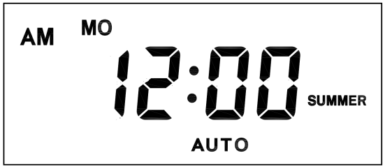
3. Set clock

Hold [CLOCK" button and [WEEK" button to adjust week.
Hold [CLOCK" button and [HOUR" button to adjust hour.
Hold [CLOCK" button and [MINUTE" button to adjust minute.
Hold [CLOCK" button and [TIMER" button to select 12 hour/24 hour display.
Hold [CLOCK" button and [ON/AUTO/OFF" button to enable/disable DST (daylight-saving-time).
4. Set timer
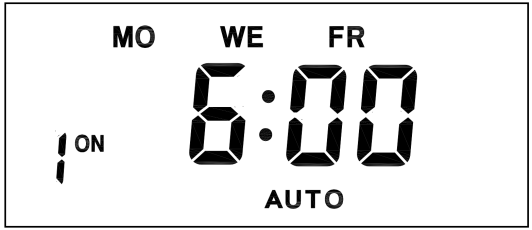
Press [TIMER" button, select and set timer. Setting rotation : 1on, 1off, 2on, 2off, ...... , 10on, 10off.
Press [HOUR" button to set hour for timer.
Press [MIN" button to set minute for timer.
Press [WEEK" button to set weekday for timer. Multiple weekdays can be selected. ex: if selected [MO", the timer will only apply on every Monday; if selected [ MO, WE, FR", the timer will apply on every Monday, Wednesday and Friday.

Press [RES/RCL" button to cancel the selected on or off timer. The screen will show "-- -- : -- --" , the timer is canceled.
Press [RES/RCL" button again to reactivate the timer.

When timers are set, press [CLOCK" to quit timer setting and return to clock.
5. Random function

Press [RANDOM" button to activate random function, press again to cancel function.
System only runs random function when [AUTO" is on.
Random function will automatically start the timer from 2 to 32 minutes after the setting.
ex : if timer 1on was set to 19:30 with the random function on, the timer will activate randomly between 19:33 to 20:03.
if timer 1off was set to 23:00 with the random function on, the timer will activate randomly between 23:02 to 23:32.
To avoid overlapping, make sure to leave a minimum of 31 minutes gap between different sets of timer.
6. Manual control
Displayed features:
ON : socket turns on.
OFF : socket turns off.
AUTO : socket turns on/off automatically via timer.
Manual ON setting
Press [ON/AUTO/OFF" button to switch from [AUTO" to [ON".
This mode allows socket of the device to power up. Power indicator will light up.
Manual OFF setting
Press [ON/AUTO/OFF" button to switch from [AUTO" to [OFF".
This mode turns socket of the device off. Power indicators will turn off.
7. Electrical parameters
Operating voltage : 230VAC
Battery : NiMh 1.2V
Power consumption : < 0.9W
Response time : 1 minute
Power output : 230VAC/16A/3680W
Q&A
Q: Why won`t my timer turn on?
A: It`s out of battery, you can charge the timer by plugging onto any power outlet. Charge the device for at least 15 minutes. Then press [RESET " button to reset the device.
Q: Can I set seconds of the timer?
A: No, the smallest time unit is minute.
Q: Does my timer keeps old settings without being plugged onto a power outlet?
A: Yes, the timer has an internal battery, it allows the timer to save settings without a power outlet.
Q: Is the battery rechargeable?
A: Yes, the battery is rechargeable. We recommend to charge it for 4 hours so the battery is fully charged.
Q: Does the timer needs internet connection?
A: The timer does not need internet.
Q: Does the screen have back light function?
A: It doesn`t support back light.
digital timer, digital timer socket, electronic timer socket, timer socket
NINGBO COWELL ELECTRONICS & TECHNOLOGY CO., LTD , https://www.cowellsocket.com
