
introduction
This paper is designed to be a dot matrix LED text display with convenient, scalable and low price.
The way to reduce costs is: 1. Update the LED display content with the Bluetooth data transmission function of almost everyone's mobile phone, eliminating the cost of the professional PC software and control card, and the operation is simpler; 2. Single display The content is in 5 to 30 Chinese characters or English letters, and since the display content is small, the expansion circuit can be simplified.
1 system design
1.1 System components
The system consists of a Bluetooth-enabled smartphone and an LED display. Among them, the LED display consists of single-chip microcomputer, LED dot matrix module, font chip, Bluetooth receiver module, 5V switching power supply and 3.3V voltage regulator circuit, as shown in Figure 1. The system works as follows: The user edits the “data†through the smartphone's notepad and sends it via the wireless Bluetooth to the Bluetooth receiver module on the display. The main control MCU reads the “data†received by the Bluetooth receiving module and processes it. “Data†consists of “Control Command†and “Display Contentâ€, and the two parts of data are separated by custom signatures. The “control command†is used to set the brightness of the display screen, the moving speed of the display content and the moving direction; and the MCU finds the corresponding 32-byte display code in the font chip according to the received character code of the “display contentâ€. Screen display.

Figure 1 System composition
1.2 LED dot matrix working principle
The LED dot matrix display can be made up of several pieces of each LED unit board as needed for display. The universal LED unit board consists of 2 16&TImes; 16 dot matrix LEDs with dimensions of 160*320mm.
The unit board works as follows:
Each board has 16 rows and 32 columns, and the data is displayed in a traditional determinant scanning mode. Usually, in order to reduce the flicker and increase the scanning speed, 1/4 scan is used, that is, 16 lines are divided into 4 4 lines, and the same order corresponding rows in 4 4 lines are simultaneously strobed at the same time, so that scanning can be completed 4 times. A 16-line scan is displayed. The column control is undertaken by the 74HC595, and there are 16 pieces on each unit board, each of which controls 4 rows and 8 columns of dot matrix units. The row control is carried out by a single decoder 74LS138, each time strobing the same four rows of four rows of the cell board. To ensure normal current drive (brightness), the output of the 74LS138 is amplified by the AMP4593 driver. There are 4 pieces per cell board, each driving 4 rows. The 16-piece 74HC595 is connected in cascade mode. Since each of the 4 rows and 32 columns requires 4 74HC595, 16 rows and 32 columns are 16 slices. Set the first four rows of four 74HC595 serial numbers 1, 2, 3, 4, the second four rows of four 74HC595 serial numbers 5, 6, 7, 8, and so on. The data output terminal of each chip is connected to the input end of the next chip, and the data is serially input from the input end of the first chip. One bit is sequentially shifted in by the shift pulse, and 8 & TImes; 16 pulses are used first. The shifted data is shifted to the lowest bit of the 16th chip (also the output of the slice). After all the data is moved in, the complete content of one board can be displayed, and the software design can be displayed according to this rule. If there are more words displayed, there will be more spliced ​​LED unit boards, and more shift pulses are required to display the full contents of one screen. This display mode requires the master microcontroller to have a higher instruction execution speed, otherwise there will be a flickering sensation. The schematic diagram of the lattice unit board is shown in Figure 2.
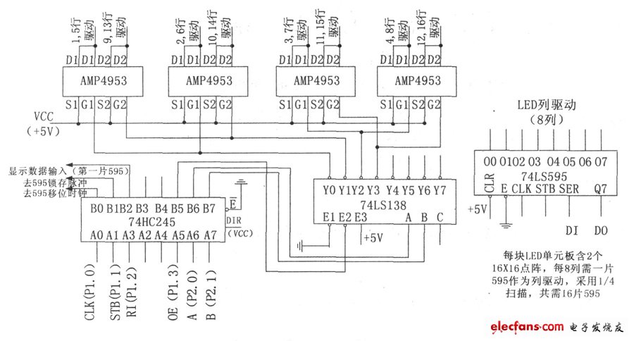
Figure 2 lattice unit board schematic
ATS48 offers reliable, robust and high performance Soft Starters for your motors with unique Torque Control Systems (TCS).
3 Phase For Motor Control Inverter,Mini Inverter ,Inverter Circuit Board ,Schneider Inverter Charger
Wuxi Trenty Machinery & Equipment Co., Ltd. , https://www.elec-inverter.com