
introduction
At present, PLC (Power Line Carrier Technology) is quite mature. Based on the PLC idea, while the terminal supplies power to the detection module through the bus, the detection module can couple the alarm information into the power line and send it to the monitoring terminal. Because the transmission speed of electrical signals is very fast and the bus time is short, it will not affect the decoding of the terminal because there are multiple sets of signals simultaneously on the bus, so that the entire system can use only one bus to realize the power supply of the detection module and the alarm information. transmission.
In this paper, the anti-theft alarm system based on the single bus network obtains the AC pulse signal from the bus through the signal extraction circuit, and sends it to the decoding chip for information decoding after amplification. Finally, the information processing and human-computer interaction are realized through the single-chip computer and the PC.
Overall system block diagram
The system is mainly composed of two parts: detection and terminal.
The detection part includes multiple probes to monitor each door condition separately, as shown in Figure 1.
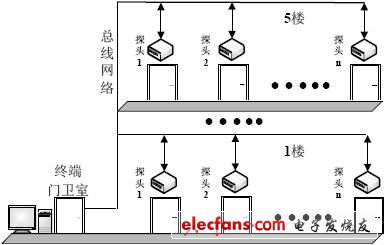
Figure 1 System network control
The terminal part mainly realizes the functions of information extraction, information decoding, information processing and human-computer interaction. Decode the extracted signal through the encoding chip PT2272, send it to the single-chip microcomputer for information processing after level triggering and voltage stabilization, and the extended function can also send the information into the PC through serial port communication to make the system function more perfect.
System hardware design
System codec principle
The coding signal sent by the coding chip PT2262 is composed of address code, data code and synchronization code to form a complete code word. After the decoder chip PT2272 receives the signal, the VT pin outputs a high level after its address code is compared and checked twice. At the same time, the corresponding data pin also outputs a high level or a low level. If the PT2262 is always powered, the encoding chip will also continuously transmit. When the PT2262 is powered up, it outputs a modulated 60Hz serial data signal per frame, otherwise the PT2262 does not work.
The decoder chip PT2272 has different suffixes, such as L4 / M4 / L6 / M6. Where L represents the latched output, as long as the data is successfully received, it will remain at the corresponding level until the next time the remote control data changes. M means non-latching output. The suffix data indicates that there are several parallel control channels.
Principles of Information Transmission
Because the encoding chip sends the segmented pulse waveform group to the bus, the alarm information can be coupled to the bus through a capacitor. The codec chip in this design uses the commonly used 2262 / 1.2M = 2272 / 200K combination, and the output signal is a 60Hz pulse signal.
When the frequency is fixed, in order to make the signal coupling into the bus without distortion, the larger the capacitance, the better. However, the larger the capacitance, the longer the discharge time, which leads to waveform distortion. Through the test, the fidelity effect is best when the capacitance value is 100mf.
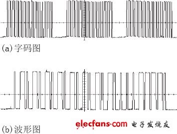
Figure 2 Alarm signal waveform
Figure 2 is a section of the alarm signal waveform intercepted in the bus. It can be seen that Figure 2 (a) is a group of words, and each group of words is separated by a synchronization code. Figure 2 (b) is an enlarged set of word codes. A word code is composed of a 12-bit AD code (address code plus data code, 8-bit address code plus 4 data codes in the design), two for each AD bit Pulse means: two narrow pulses indicate "0"; two wide pulses indicate "1"; one narrow pulse and one wide pulse indicate "F", which is "floating" of the address code.
PT2262 transmits at least 4 groups of code each time it is transmitted. PT2272 will drive the VT terminal to synchronize to high level only after detecting the same address code and data code twice in succession, and at the same time put the "1" in the data code Drive the corresponding output to high level. Otherwise, the decoding is invalid.
Working principle of detection module
Because this design uses infrared photoelectric sensors as sensitive originals, false alarms will occur when there is sunlight interference, so an anti-interference circuit needs to be designed to solve this problem to reduce the probability of false alarms.
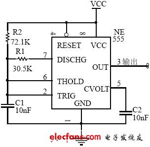
Figure 3 Square wave generator
The circuit performs 1000 square wave oscillation on the voltage through the NE555 timer and inputs the photoelectric sensor, as shown in Figure 3. When there is sunlight interference, after filtering through LM567, the output voltage is almost zero, PT2262 does not work, and no alarm will be generated. Only when the photoelectric sensor is reflected, the output voltage of the LM567 filter can make the PT2262 chip work, thus an alarm occurs.
The hendlight wiring harness apply for household appliance, automotive, motocycle, bus, bike, truck, medical equipment.
Yacenter has experienced QC to check the products in each process, from developing samples to bulk, to make sure the best quality of goods. Timely communication with customers is so important during our cooperation.
If you can't find the exact product you need in the pictures,please don't go away.Just contact me freely or send your sample and drawing to us.We will reply you as soon as possible.
Headlight Wiring Harness,Headlight Harness,Headlamp Wiring Harness,Headlight Wiring Kit
Dongguan YAC Electric Co,. LTD. , https://www.yacentercn.com