Microwave induction control circuit Figure 1 is a schematic diagram of a microwave control circuit made with discrete components.
In Figure 1, the high-frequency transistor VT1 generates self-oscillation under the positive feedback of the capacitor C1. The high-frequency electromagnetic wave generated by the oscillation is radiated by the antenna to the surrounding space, and a three-dimensional microwave field is generated around the antenna. When there is a moving object In this three-dimensional space, the electromagnetic waves reflected by the movement of the object are received by the antenna, causing the amplitude and frequency of the self-excited oscillation of VT1 to change, and these changes become voltages that fluctuate with the movement of the object through the integrating circuit composed of R2 and C3 After this voltage is amplified by VT2, it can produce a voltage change of 2.5-6.7V on its collector (the voltage change is proportional to the speed of the object and the distance from the antenna). This changed voltage is sent to the dual-limit voltage comparator composed of IC1 and IC2. Whether the potential of the VT2 collector to IC1 pin 2 is lower than the pin ③, or the VT2 collector to IC2 pin potential is higher than the pin ⑥, IC ①feet and IC2 ⑦ feet will output high level, these two high levels are rectified by VD1, VD2 and added to the base of VT3 to make it conductive, and then relay K gets electric pull-in, which is controlled. Circuit control.
In Figure 1, the inductance L1 is formed by winding 5 turns of φ0.51mm high-strength enameled wire on a φ5mm ballpoint pen core; the antenna is a metal rod antenna with a length of about 15cm used for short-wave radios. The parameters of other components are shown in Figure 1. C1 should be perpendicular to L1 during installation.
The microwave control circuit works according to the Doppler effect: a fixed high-frequency signal (generally 400-800MHZ) is generated by the local oscillation circuit, and radiated to the surrounding space through the antenna. When an object moves within a certain distance near the antenna, the high-frequency signal will be reflected back by the moving object and then received by the antenna, which causes the oscillation frequency and signal amplitude of the original oscillation circuit to change. The integration circuit is then used to extract this changed signal. After amplification, comparison and other processing, a control signal is formed, so that the control execution circuit (such as high-power thyristor, relay, etc.) is started, and the purpose of automatic control is achieved.

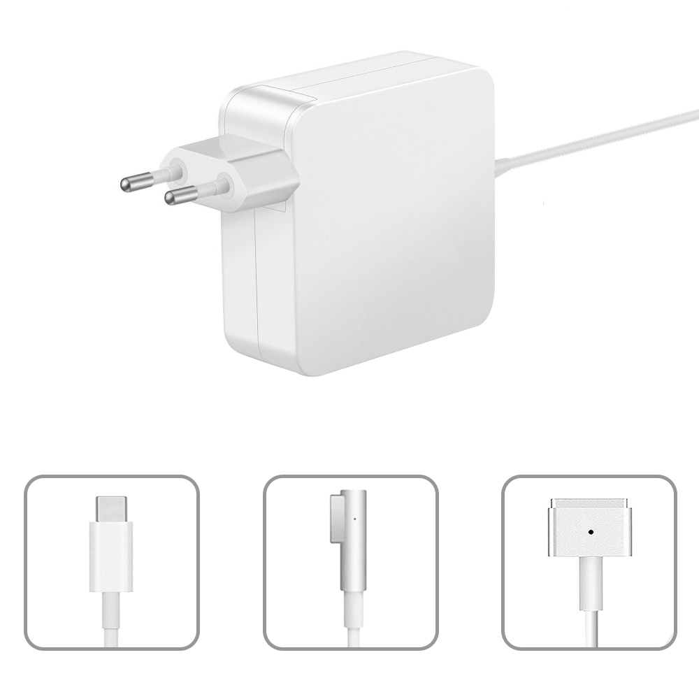
The 60W Macbook Charger with MagSafe1 or Magsafe 2 Power Adapter has a magnetic DC connector, so if someone trips on it, the power cord disconnects harmlessly, keeping your MacBook Air safe. It also helps prevent the cable from fraying or weakening over time. Additionally, the magnetic DC helps guide the plug into the system for a quick and safe connection.
60W Apple charger usb c,60w charger macbook air,macbook 60w charger
Shenzhen Waweis Technology Co., Ltd. , https://www.huaweishiadapter.com
