
Keywords: single-chip wireless transceiver chip nRF401, wireless communication protocol, wireless meter reading
The nRF401 single-chip wireless transceiver chip has few peripheral components and can be directly connected to the serial port of the single-chip computer. It provides a better solution for the design of short-range wireless data transmission applications such as intelligent wireless meter reading, and is widely used in many fields. However, due to the particularity of wireless communication, some external factors will affect the wireless transmission of data, so effective methods need to be adopted to ensure communication. In order to effectively apply wireless communication, a communication channel model for wireless data transmission is established here to understand and discuss the impact of external factors on wireless data transmission, analyze the causes and links of errors and how to effectively transmit data, and finally provide a The actual wireless communication protocol used.
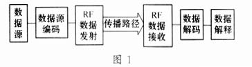
1 Communication channel model and its analysis In order to analyze the factors that affect wireless communication, we have established a wireless communication channel model. Communication channel refers to a complete channel from data transmission to reception. It includes generating data sources, encoding, transmitting, receiving, decoding, etc., as shown in Figure 1.
1.1 Data source Data source refers to the source of data generation. The data source is different in different applications. It may be the A / D data value of a temperature sensor, a file in the computer, or the user input in the keyboard. A button. The data is less likely to be wrong here, and it is easier to find through hardware or software.
1.2 Data encoding Data encoding mainly includes parallel-to-serial and encoding information added for reliable transmission. What nRF401 needs is a serial data format, which is usually completed by a single-chip microcomputer UART (Universal Asynchronous Transmission), and sometimes can also be done by software I / O simulation. The data is unlikely to be wrong here, and can be tracked and found.
1.3 Data transmission Data transmission is accomplished through the transmission function of the single-chip wireless transceiver chip nRF401. nRF401 uses PLL frequency synthesis and FSK modulation technology, its design is reliable, but external factors such as inappropriate power supply, poor PCB design and layout, noise, inappropriate modulation voltage level, and inappropriate antenna load can An error that caused data flow. The key points to solve need to be based on good RF PCB design, select peripheral components that meet the requirements, and pay attention to power supply (good power supply filtering, as far as possible without switching power supply), by comprehensively adopting the above measures, you can reduce the factors that cause data flow errors Ideal effect.
1.4 Propagation path The propagation path is the path from radio wave to transmission. The propagation loss will directly affect the communication effect. Data errors are most likely to occur at this stage. Because the interference in the frequency band or the loss of the RF signal in the propagation path reduces the sensitivity, and multipath and attenuation may also cause the receiver to receive erroneous data. Propagation loss includes free space loss and other losses. Other major losses include: atmospheric, rainfall, cloud, fog loss; tree shelter loss; building and other shelter losses; in addition, sudden interference can also lead to data errors . The following uses free space loss as an example to predict propagation.
The so-called free-space propagation refers to the propagation of radio waves when there is an infinite vacuum around the antenna. It is an ideal propagation condition. The free-space propagation loss is related to the distance and the operating frequency. The following formula illustrates the loss of radio wave propagation in free space:
[Los] (dB) = 32.44 + 20lgd + 20lgf
In the formula, Los is the propagation loss, the unit is dB; d is the distance, the unit is km; f is the operating frequency, the unit is MHz.
It can be seen from the above formula that the propagation loss (also called attenuation) of radio waves in free space is only related to the operating frequency f and the propagation distance d. When f or d is doubled, Los will increase by 6dB respectively.
The following example illustrates the propagation distance of a wireless system (based on nRF401) with a working frequency of 433.92MHz, a transmit power of + 10dBm (10mW), and a receiving sensitivity of -105dBm in free space:
(1) By transmitting power + 10dBm, receiving sensitivity is -105dBm, then Los = 115dB;
(2) Calculated from Los and f, d = 9.7 km.
This is the transmission distance under ideal conditions. In practical applications, it will be lower than this value. This is because wireless communication is affected by various external factors, such as the loss caused by the atmosphere, barriers, multipath, etc. When the value is included in the above formula, the approximate communication distance can be calculated. Assuming that the loss caused by the atmosphere, occlusion, etc. is 25 dB, the communication distance can be calculated as: d = 1.7 km. It can also be seen that the propagation loss has a great influence on the reliability of data transmission.
1.5 The data receiving and receiving process is completed by the receiving function of the single-chip wireless transceiver chip nRF401. When no signal is received, nRF401 will output random data because of its high sensitivity. When the transmitter transmits, the random data output of the receiver is suppressed, and the output is real data. In-band interference and frequency drop may cause the receiver to receive erroneous data. As in the case of data transmission, reasonable PCB design and layout, good power supply, etc. will produce better results.
1.6 Data decoding The data output from nRF401 is serial data, which can usually be processed by the UART of the microcontroller, or implemented by software. The possibility of data errors in this process is very small and easy to be tracked. If the error occurs before this, it can be found through software based on the frame error.
1.7 Data interpretation Data interpretation is usually implemented in software. Error detection and correction are also implemented at this stage. Data errors are unlikely to occur at this stage and are easy to track.
2 Basic requirements and design of wireless communication protocol After analyzing the wireless communication channel model and understanding and discussing the impact of external factors on wireless data transmission, we can design a practical wireless communication protocol accordingly.
2.1 Identification of start code and noise This is because nRF401 has a relatively high sensitivity. Due to the characteristics of nRF401, nRF401 will output random data when no signal is received, so the first thing of the protocol is to be able to identify noise and effective data. Noise appears in random bytes and there is no obvious way. An ideal noise source should be able to produce every possible combination of bytes of information. This characteristic of noise makes it very difficult to find a combination of bytes as the beginning of a valid packet, but in reality, noise is not ideal. After testing and experiments, we found that 0xFF followed by 0x00 is not easy to occur in noise, and the transmission protocol should add the start byte 0xFF followed by 0 before the data packet.
The start of the sending protocol should be a byte of arbitrary content such as 0xAA (this is because the data of the first byte is easily lost when sending), and then 0xFF followed by a 0x00; the receiving protocol stipulates that only receiving starts with 0xFF followed by a 00x00 Package.
2.2 Error detection In order to find errors that may occur in data transmission, it is necessary to perform error detection on the received data. Error detection can be achieved by analyzing the data before transmitting and then adding this analysis result to the data packet, called the supervisory bit; comparing the supervisory bit appended to the information bit at the receiving end, if the two are different , The package is wrong. There are many methods of error detection, parity check, sum check and CRC check.
Parity check and sum check are relatively common and easy to implement methods. The parity check method is illustrated below as an example.
Example 1: Transmit data 1 0 1 0 1 0 1 0, followed by the parity flag bit, this is the even flag (1), then sent as 1 0 1 0 1 0 1 0 1 received 0 0 1 0 1 0 1 0 1. The first 8 bits of parity are compared with 1, which is incorrect, so the reception is wrong. Parity is easy to implement, but it is the most unreliable because it can only find an odd number of errors.
Another form of error checking is sum checking. Sum check is to add all the data bytes first, and then truncate the result to the required bit length and transmit it as a syndrome. The following illustrates with Example 2.
Example 2:
4 bytes 1
109 bytes 2
65 bytes 3
204 bytes 4
The 126 8 bit checksum checksum can detect more errors than parity, but when the byte order is reversed, the checksum cannot be found because it cannot find the wrong order. If higher reliability is required, CRC coding and CCITT16 error detection coding can be used. In theory, burst or random errors below 16 bits can be completely detected. For specific principles and implementation methods, please refer to relevant information.
2.3 Error correction The purpose of error correction is to add some additional information when sending data encoding to detect and correct errors that occur in data transmission. Forward error correction methods include Hamming codes, cyclic codes, and convolutional codes.
Although some complex algorithms have good error correction and detection effects, for many people who are new to the design of wireless communication protocols, it may require a lot of energy to understand the relevant mathematical knowledge. Therefore, here we introduce a repeated code to Error correction algorithm, it is suitable for simple and practical communication protocol, programming is also very easy to implement, it is applied in wireless data transmission system designed by nRF401. The following is a forward error correction method suitable for many wireless data transmission. The data is copied twice in the packet (a total of 3 copies). At the receiving end, the first copy is checked for errors. If there is an error, the remaining two backups are used to correct the error.
The error is corrected by comparing each bit in the three backup data. If two or more bits are 0, the correct one should be 0. Such as:
0 0 0 0 1 0 1 1 copy 1 (error byte)
1 0 1 0 1 0 1 0 copy 2
1 0 1 1 1 0 1 0 copy 3
1 0 1 0 1 0 1 0 The bytes that have been corrected can be selected as triple judgment or quintuple judgment in actual application.
3 Basic requirements of wireless communication protocol design According to the analysis of the wireless channel model, we can understand that wireless communication protocol has the following basic requirements:
· Minimum overhead: The wireless transmission process is affected by noise or interference, etc., and error codes will occur. For this reason, various error correction codes should be performed on the data during transmission. Different coding methods have different error correction and detection capabilities, and some codes can only detect and not correct errors. Generally speaking, the larger the proportion of supervisory bit symbols, the stronger the error correction and detection capability. Error correction coding improves the reliability of transmission at the expense of reducing the transmission rate of information. Therefore, increasing the amount of information must be the least of the required information to ensure the efficiency of coding.
Reliability: A wireless communication protocol should be able to effectively detect and correct data errors.
Optimized wireless function: A wireless communication protocol should enable the device to work in an optimized manner that can make full use of the characteristics of the transmitter and receiver.
references
2 Liu Fuquan. Error correction coding and application. Harbin: Harbin Ship Engineering College Press, 1993
USB Cable
USB cable assemblies are some of the most popular cable types available, used mostly to connect computers to peripheral devices such as cameras, camcorders, printers, scanners, and more.There are many USB connector types of cable:USB A to USB C,USB C to type-C,USB A 3.1,ect..


Mobile Data Cable Types,3 in 1 Data Cable,Mobile Data Cable,Magnetic Data Cable Type C
Pogo Technology International Ltd , https://www.pogomedical.com