
Self-made FM transmitter
1) High frequency triode V1 and capacitors C3, C5, C6 form a capacitor three-point oscillator 2) C4, L form a resonator: the resonance frequency is the emission frequency of the FM microphone, according to the parameters of the components in the figure, the emission frequency can be 88 Between ~ 108MHZ, it just covers the receiving frequency of the FM radio. By adjusting the value of L (stretching or compressing the coil L), the transmission frequency can be easily changed to avoid the FM radio station. The transmitted signal is coupled to the antenna through C4 and then transmitted.
3) R4 is the base bias resistor of V1, which provides a certain base current to the transistor, so that V1 works in the amplification region.
4) R5 is a DC feedback resistor, which plays a role in stabilizing the working point of the transistor.
5) Microphone MIC collects external sound signals.
6) Resistor R3 provides a certain DC bias voltage for the MIC. The larger the resistance of R3, the weaker the microphone's sensitivity to collecting sound, and the smaller the resistance, the higher the microphone's sensitivity.
7) The AC sound signal collected by the microphone is sent to the base of the triode through C2 coupling and R2 matching.
8) The two diodes D1 and D2 in the circuit are connected in anti-parallel, mainly functioning as a bidirectional limiting. The diode's conduction voltage is only 0.7V. If the signal voltage exceeds 0.7V, it will be shunted by the diode, which can ensure the sound The amplitude of the signal can be limited to plus or minus 0.7V. Excessively strong sound signal will over-modulate the transistor, causing sound distortion and even unable to work normally.
9) CK is an external signal output socket. You can introduce external sound signal sources such as TV headphone jacks or Walkman headphone jacks into a FM transmitter through a dedicated connection line. The external sound signal is sent to R1 after attenuation and D1 and D2 amplitude limiting. The base of the transistor is frequency modulated.
10) The light-emitting diode D3 in the circuit is used to indicate the working state. It will light up when the FM microphone is powered on, and R6 is the current-limiting resistance of the light-emitting diode. C8 and C9 are power supply filter capacitors. Because large capacitors are generally made by winding process, the equivalent inductance is relatively large. Paralleling a small capacitor C8 can make the high-frequency internal resistance of the power supply.
11) K1 and K2 in the circuit are a switch, it has three different positions, turn off the power when dialed to the far left, K1 and K2 on the far right are used as FM microphones, K1 is on and K2 is off in the middle Use as a wireless transponder, because the microphone does not work as a wireless transponder, but the microphone consumes a certain static current, so disconnecting K2 can reduce power consumption and extend battery life.
Frequency modulation is achieved by changing the capacitance between the base and the emitter of the transistor. When the sound voltage signal is applied to the base of the transistor, the capacitance between the base and the emitter of the transistor will be synchronized with the size of the sound voltage signal Changes, at the same time make the transmission frequency of the transistor change, to achieve frequency modulation. 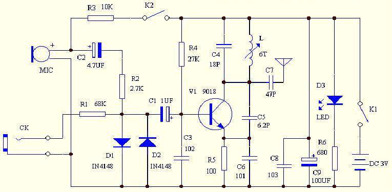
Transmitter circuit diagram 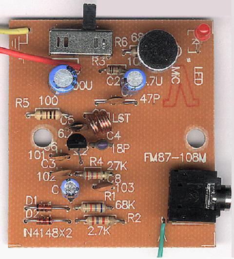
Transmitter finished picture 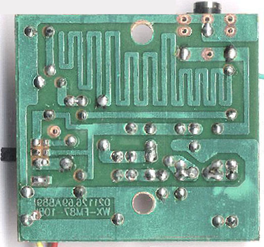
Transmitter PCB illustration (the broken line part in the pcb diagram is an internal antenna. After the design is completed, it is not necessary to match the antenna. It can work after simple debugging! If you feel that the transmission distance is not ideal, you can increase the power supply voltage appropriately. The 9018 in this circuit can withstand voltages within 12V; it can also add a level of modulation and amplification in the circuit, which can also effectively increase the transmission distance !!! The receiver can be replaced with an FM radio !!!)
Dongguan Guancheng Precision Plastic Manufacturing Co., Ltd. , https://www.dpowergo.com