1. Basic introduction of digital tube
Let me give you a schematic diagram, as shown in Figure 1.
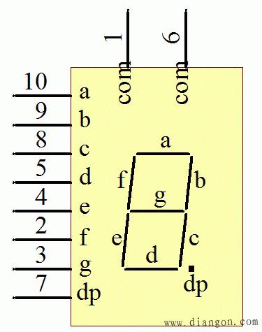
Figure 1 digital tube schematic
This is a more common schematic of the digital tube. There are a total of 6 digital tubes on our board. With the learning of LED small lights in front, digital tube learning will be much easier. As can be seen from Figure 1, the digital tube has a total of 8 segments a, b, c, d, e, f, g, dp, but in fact, each of the 8 segments is an LED small lamp, so the digital tube It is composed of 8 LED small lights. Let's take a look at the internal structure of the digital tube.
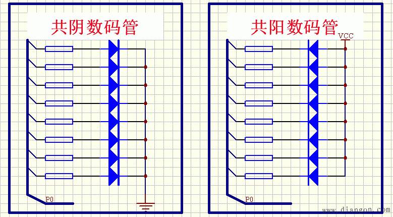
Figure 2 digital tube structure diagram
The digital tube is divided into a common digital tube and a common digital tube. The so-called common cathode digital tube is that the cathodes of the 8 LED small lamps are connected together, that is, the cathode is a common end, and the anode is used to control whether the small lamp is on or off. . In the same way, the common anode is the anode that is connected together. You can carefully study Figure 1 below. Careful students will also find that there are 2 coms on the digital tube, which is actually the public end of our digital tube. Why there are two, I personally think that on the one hand, there are two that can play a symmetrical effect, just 10 pins. On the other hand, the current through the common terminal is larger. We learned in junior high school, and the sum of parallel circuit currents. Equal to the total current, with 2 com can average the common current to 2 pins, reducing the current on the line.
As can be seen from the circuit diagram of our board, the digital tube we use is a common digital tube, as shown in the figure.

Figure 3 common digital tube circuit
Their com is received on the positive pole. Of course, similar to the LED small lamp circuit, the 74HC138 controls the conduction of the triode to control the current of the whole digital tube. Let us first look at the DS1 digital tube. As can be seen from the schematic diagram, the triode that controls DS1 is Q17, and the pin that controls Q17 is LEDS0, which corresponds to the output of Y0 on the upper side of 74HC138.
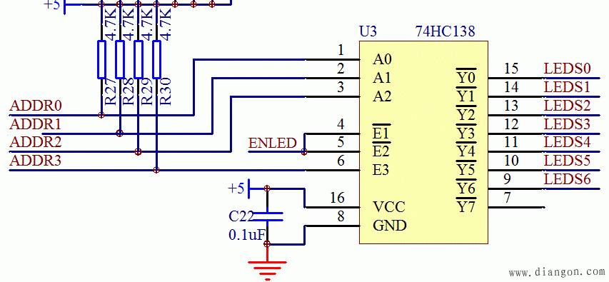
Figure 474HC138 control chart
Our current goal is to make the LEDS0 pin output low level. I believe that you can now write the four input states of ADDR0, ADDR1, ADDR2, ADDR3, ENLED independently according to what you have learned before. Now, don't be lazy, Go and write according to the manual of 138. You don't need to remember these conclusions, but you will write once, and after a few workouts, you will know how to solve the problem by encountering similar chips.
The digital tube is usually used to display numbers. The six digital tubes on our board are customarily called 6 bits. The control bit is 74HC138. The 8 LED small lights inside the digital tube are called the segments of the digital tube, then the segment selection of the digital tube (that is, the bright and extinguishing of the segment) is controlled by the P0 port and driven by the 74HC245.
2, the true value of the digital tube
The 8 segments of the digital tube, we directly control as 8 LED small lights, that is a, b, c, d, e, f, g, dp a total of 8 LED small lights. We can easily see through Figure 1. If we light the two LED small lights b and c, that is, the b and c segments of the digital tube, all the other segments are extinguished, then the digital tube DS1 can be made. Display a number 1, then this time the actual binary value of P0 is 0b11111001, hexadecimal is 0xF9. Then we write a program to go in and see if the digital tube shows it.
#include//Library file containing registers
sbitADDR0=P1^0;
sbitADDR1=P1^1;
sbitADDR2=P1^2;
sbitADDR3=P1^3;
sbitENLED=P1^4;
Voidmain()
{
Unsignedcharj=0;
Unsignedinti=0;
ENLED=0;
ADDR0=0;
ADDR1=0;
ADDR2=0;
ADDR3=1;//74HC138 turn on the transistor Q17
While(1)// program dead loop
{
P0=0xF9;//Open the digital tube b and c segments
}
}
Everyone compiles this program, downloading it to the microcontroller will find that the rightmost digital tube successfully displays 1 this number.
In the same way, we can successfully display other numbers on the digital tube, and the number displayed by the digital tube corresponds to the assignment of P0. We call it the truth table of the digital tube. Let's take a look at the digital tube truth table of our circuit diagram. Note that the numbers shown in this truth table do not have a decimal point.
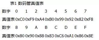
You can change the value of P0 in the program of the digital tube display 1 to the number in the truth table in Table 5-1, and display the number displayed by the digital tube.
3, the static display of the digital tube
After learning the 74HC138 in the third lesson, we learned that the 74HC138 can only make one output port low at a time, that is, in one moment, we can only let one digital tube display, always strobe the digital tube and can The signal of our P0 bus to change the value of this digital tube, we can understand the static display of the digital tube.
The static display of the digital tube is corresponding to the dynamic display. The static display is OK for one or two digital tubes, and the meaning of the static display is lost. In this lesson, we first use a static display of the digital tube to implement a simple stopwatch, which lays the foundation for the dynamic display of the next lesson.
First introduce the keyword code of a 51 single chip. When we define variables in the previous course, we usually use the two keywords unsignedchar or unsignedint. The variables defined in this are all placed in the RAM of our microcontroller. We can change the value of this variable at will. But there is a constant that we want to use in the program, but we don't change the value. We can add a code keyword to modify it. After the modification, the value will be stored in our program space. Flash, this can greatly save the use of RAM of our microcontroller, after all, our RAM space is relatively small, and the program space is very large. For example, the digital tube truth table we are going to use now, let's take a look at our program below.
#include//Library file containing registers
sbitLED=P0^0;
sbitADDR0=P1^0;
sbitADDR1=P1^1;
sbitADDR2=P1^2;
sbitADDR3=P1^3;
sbitENLED=P1^4;
unsignedcharcodeLedChar[]={
0xC0, 0xF9, 0xA4, 0xB0, 0x99, 0x92, 0x82, 0xF8,
0x80, 0x90, 0x88, 0x83, 0xC6, 0xA1, 0x86, 0x8e
};//Use array to store the digital tube truth table, the next lesson introduces the array
Voidmain()
{
Unsignedcharcounter=0;
Unsignedcharj=0;
ENLED=0; ADDR0=0; ADDR1=0;
ADDR2=0; ADDR3=1; P0=0XFF; //74HC138 and P0 initialization part
TMOD=0x01; //Set timer 0 to mode 1
TH0=0xB8;
TL0=0x00; //the initial value of the timing value
TR0=1; //Open timer 0
While(1)
{
If(1==TF0) //Check if timer 0 overflows
{
TF0=0;
TH0=0xB8; //Re-assign after overflow
TL0=0x00;
Counter++;
If(50==counter)//Check if timer 0 overflow reaches 50 times
{
Counter=0; / / counter clear 0, recount
P0=LedChar[j++];//Send the corresponding value in the array to P0
If(16==j)//When displayed to F, return to 0 to restart
{
j=0;
}
}
}
}
}
Absolute Linear Encoders,Custom Absolute Encoder,Rotary Encoder Magnetic,Miniature Absolute Encoder
Yuheng Optics Co., Ltd.(Changchun) , https://www.yhenoptics.com
