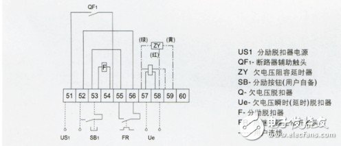
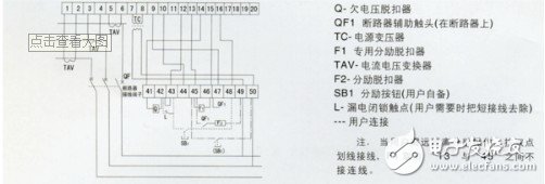
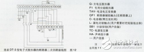
This article mainly introduces the universal circuit breaker, and focuses on the wiring method and wiring diagram of the universal circuit breaker.
Universal circuit breakerCircuit breaker refers to a switching device that can close, carry and break current under normal circuit conditions, and can close, carry and break current under abnormal circuit conditions within a specified time. Circuit breakers are divided into high-voltage circuit breakers and low-voltage circuit breakers according to their scope of use. The division of high and low voltage is relatively fuzzy. Generally, those above 3kV are called high-voltage electrical appliances. Circuit breakers can be used to distribute electrical energy, start asynchronous motors infrequently, and protect power lines and motors. They can automatically cut off the circuit when they experience serious overload, short circuit, and undervoltage faults. Its function is equivalent to a fuse switch Combination with overheating and underheating relays, etc. Moreover, it is generally not necessary to change parts after breaking the fault current. At present, it has been widely used.
In the generation, transmission, and use of electricity, power distribution is an extremely important link. The power distribution system includes transformers and various high- and low-voltage electrical equipment, and low-voltage circuit breakers are widely used electrical appliances.

working principle
Circuit breakers are generally composed of contact system, arc extinguishing system, operating mechanism, trip unit, shell and so on.
When a short circuit occurs, the magnetic field generated by a large current (generally 10 to 12 times) overcomes the reaction force spring, the trip unit pulls the operating mechanism, and the switch instantaneously trips. When overloaded, the current becomes larger, the heat generation increases, and the bimetal deforms to a certain extent to push the mechanism to move (the larger the current, the shorter the action time).
There is an electronic type that uses a transformer to collect the current of each phase and compares it with the set value. When the current is abnormal, the microprocessor sends a signal to make the electronic trip unit drive the operating mechanism.
The function of the circuit breaker is to cut off and connect the load circuit, as well as cut off the fault circuit, to prevent the expansion of the accident and ensure safe operation. The high-voltage circuit breaker needs to break the 1500V, current 1500-2000A arc, these arcs can be stretched to 2m and still continue to burn without being extinguished. Therefore, arc extinguishing is a problem that must be solved by high-voltage circuit breakers.
The principle of arc blowing and arc extinguishing is mainly to cool the arc to weaken the thermal dissociation. On the other hand, the arc is stretched by the arc to strengthen the recombination and diffusion of charged particles, and at the same time, the charged particles in the arc gap are blown away to quickly restore the dielectric strength of the medium.
Low-voltage circuit breakers are also called automatic air switches, which can be used to connect and break load circuits, and can also be used to control motors that start infrequently. Its function is equivalent to the sum of some or all of the functions of knife switches, overcurrent relays, voltage loss relays, thermal relays and leakage protectors. It is an important protective electrical appliance in low-voltage distribution networks.
Low-voltage circuit breakers have a variety of protection functions (overload, short circuit, undervoltage protection, etc.), adjustable action value, high breaking capacity, convenient operation, safety, etc., so they are widely used. Structure and working principle The low-voltage circuit breaker is composed of operating mechanism, contacts, protection devices (various releases), arc extinguishing system, etc.
The main contact of the low-voltage circuit breaker is manually operated or electrically closed. After the main contact is closed, the free trip mechanism locks the main contact in the closing position. The coil of the overcurrent release and the thermal element of the thermal release are connected in series with the main circuit, and the coil of the undervoltage release is connected in parallel with the power supply. When the circuit is short-circuited or severely overloaded, the armature of the overcurrent release pulls in, causing the free tripping mechanism to operate, and the main contact disconnects the main circuit. When the circuit is overloaded, the heating element of the thermal trip unit will bend the bimetal and push the free trip mechanism to move. When the circuit is under-voltage, the armature of the under-voltage release is released. It also makes the free trip mechanism act. The shunt release is used for remote control. During normal operation, its coil is cut off. When distance control is required, press the start button to energize the coil.
Main features of universal circuit breakerThe characteristics of circuit breakers mainly include: rated voltage Ue; rated current In; overload protection (Ir or Irth) and short-circuit protection (Im) trip current setting range; rated short-circuit breaking current (industrial circuit breaker Icu; household circuit breaker Icn) )Wait.
Rated working voltage (Ue): This is the voltage at which the circuit breaker works under normal (uninterrupted) conditions.
Rated current (In): This is the maximum current value that a circuit breaker equipped with a special overcurrent trip relay can withstand indefinitely under the ambient temperature specified by the manufacturer, and will not exceed the temperature limit specified by the current-bearing component.
Short-circuit relay trip current setting value (Im): The short-circuit trip relay (instantaneous or short delay) is used to quickly trip the circuit breaker when a high fault current value appears, and its trip limit Im.
Rated short-circuit breaking capacity (Icu or Icn): The rated short-circuit breaking current of a circuit breaker is the highest (expected) current value that the circuit breaker can break without being damaged. The current value provided in the standard is the root mean square value of the AC component of the fault current. When calculating the standard value, the DC transient component (always appearing in the worst-case short circuit) is assumed to be zero. Industrial circuit breaker ratings (Icu) and household circuit breaker ratings (Icn) are usually given in the form of kA rms.
Short-circuit breaking capacity (Ics): The rated breaking capacity of a circuit breaker is divided into two types: the rated ultimate short-circuit breaking capacity and the rated operating short-circuit breaking capacity. The national standard "Low-Voltage Switchgear and Control Equipment Low-Voltage Circuit Breaker" (GB14048.2—94) provides the following explanations for the rated ultimate short-circuit breaking capacity and rated operating short-circuit breaking capacity of circuit breakers:
1. The rated ultimate short-circuit breaking capacity of the circuit breaker: According to the conditions specified in the prescribed experimental procedures, excluding the breaking capacity of the circuit breaker to continue to carry its rated current capacity;
2. Rated operating short-circuit breaking capacity of the circuit breaker: According to the conditions specified in the prescribed experimental procedures, including the breaking capacity of the circuit breaker to continue to carry its rated current capacity;
3. The test procedure for rated ultimate short-circuit breaking capacity is O-t-CO.
The specific test is: adjust the line current to the expected short-circuit current value (for example, 380V, 50kA), but the test button is not closed, the tested circuit breaker is in the closed position, press the test button, the circuit breaker passes 50kA short circuit current, The circuit breaker is opened immediately (open referred to as O), the circuit breaker should be intact and can be closed again. t is the intermittent time, generally 3min. At this time, the line is still in the hot standby state, and the circuit breaker is turned on again (close referred to as C) and then opened (O). (The turn-on test is to check that the circuit breaker is at the peak Electrical and thermal stability under current). This procedure is called CO. If the circuit breaker can be completely broken, its ultimate short-circuit breaking capacity is qualified.
4. The test procedure for the rated operating short-circuit breaking capacity (Icn) of the circuit breaker is O—t—CO—t—CO. It has one more CO than Icn's test procedure. After the test, the circuit breaker can completely break and extinguish the arc, and it is determined that its rated operating short-circuit breaking capacity is qualified.
Therefore, it can be seen that the rated limit short-circuit breaking capacity Icn means that the low-voltage circuit breaker can operate normally after breaking the maximum three-phase short-circuit current at the outlet end of the circuit breaker and break this short-circuit current again. As for whether it can be normal in the future The circuit breaker is not guaranteed for making and breaking; and the rated operating short-circuit breaking capacity Ics means that the circuit breaker can break normally many times when the maximum three-phase short-circuit current occurs at its outlet end.
The IEC947-2 "Low-Voltage Switchgear and Control Equipment Low-Voltage Circuit Breaker" standard stipulates: Class A circuit breakers (referring to circuit breakers with only overload and long delay and short-circuit transient) can have Ics of 25%, 50%, 75% and 100%. The Ics of class B circuit breakers (breakers with three-stage protection of overload long delay, short short delay and short circuit transient) can be 50%, 75% and 100% of Ics. Therefore, it can be seen that the rated operating short-circuit breaking capacity is a breaking current value smaller than the rated limit short-circuit breaking current. [
Generally speaking, a circuit breaker with a three-stage protection function of overload long time delay, short circuit short time delay and short circuit instantaneous action can achieve selective protection. Most main lines (including the outlet end of the transformer) use it as the main protection switch . Circuit breakers that do not have short-circuit short-time delay function (only overload long-time delay and short-circuit instantaneous two-stage protection) cannot be used for selective protection. They can only be used in branch circuits. IEC92 "Ship Electrical" points out that: a circuit breaker with three-stage protection emphasizes its short-circuit breaking capacity value, while a circuit breaker used in branch circuits should ensure that it has sufficient limit short-circuit breaking capacity value.
No matter what kind of circuit breaker, it has two important technical indicators, Icu and Ics. However, as a circuit breaker used on a branch line, it can only meet the rated limit short-circuit breaking capacity. The more common bias is that it is better to take the big, not to take the right, and think that the big insurance is taken. However, if it is too large, it will cause unnecessary waste (the same type of circuit breaker, the H type-high breaking type, is 1.3 to 1.8 times more expensive than the S type-ordinary type). Therefore, the circuit breaker on the branch line does not need to blindly pursue its operation short-circuit breaking capacity index. For the circuit breaker used on the main line, not only must meet the requirements of the rated ultimate short-circuit breaking capacity, but also should meet the requirements of the rated operating short-circuit breaking capacity. If only the rated ultimate short-circuit breaking capacity Icu is used to measure its breaking capacity, whether it is qualified or not, Will bring hidden dangers of insecurity to users.
The circuit breaker is a basic low-voltage electrical appliance. The circuit breaker has overload, short circuit and undervoltage protection functions, and has the ability to protect lines and power supplies.
The main technical indicators are rated voltage and rated current. Circuit breakers have different functions according to different applications, with many varieties and specifications, as well as many specific technical indicators.
The circuit breaker trips freely: at any time during the closing process of the circuit breaker, if the protection action turns on the tripping circuit, the circuit breaker can be completely disconnected reliably, which is called free tripping. The circuit breaker with free trip can ensure that the circuit breaker can be quickly disconnected when the circuit breaker is closed and short-circuited, which can avoid expanding the scope of the accident.
Physical wiring diagram of universal circuit breaker


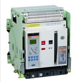
1. The DW15 universal circuit breaker is a three-dimensional arrangement, and the contact system, fast electromagnet, and left and right side panels are all installed on an insulating board. The upper part is equipped with an arc extinguishing system, and the operating mechanism can be installed directly in front or on the right side. There are "point", "close" instructions and manual disconnect button. The shunt release is installed on the upper left side, and the undervoltage release connected to the tripping shaft is installed on the back. The fast saturation current transformer or current-voltage converter is sleeved on the bus. The under-voltage delay device, thermal relay or semiconductor trip unit can be installed separately below.
2. DW15-1000, 1600, 2500, 40 universal circuit breakers
The circuit breaker has a three-dimensional layout, a contact system, and the operating mechanism is installed on an iron frame. There is an arc extinguishing system on the upper part and an operating mechanism on the right. "On" and "off" instructions and manual "on" and "off" buttons. The shunt release and undervoltage release are installed on the left side. The high-speed saturation current transformer or current-voltage converter is sheathed on the lower bus. The under-voltage delay device, thermal relay or semiconductor trip unit can be installed separately below.
ConclusionThis is the end of the relevant introduction about universal circuit breakers. I hope this article can give you a deeper understanding of universal circuit breakers.
Related reading recommendation: universal circuit breaker closing steps Related reading recommendation: universal circuit breaker working principleTpu Phone Case,Tpu Silicone Case,Soft Tpu Case,Tpu Protective Case
Guangzhou Jiaqi International Trade Co., Ltd , https://www.make-case.com
