A frequency converter (Variable-frequency Drive, VFD) is a power control device that uses frequency conversion technology and microelectronics technology to control an AC motor by changing the frequency of the motor's working power supply.
The frequency converter is mainly composed of rectifier (AC to DC), filtering, inverter (DC to AC), braking unit, drive unit, detection unit and micro-processing unit.
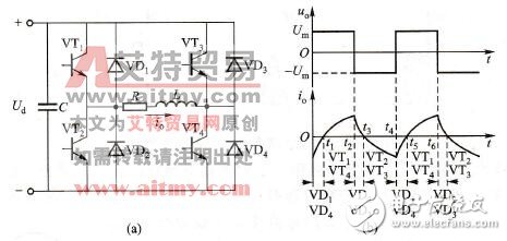
Principle of inverter circuitThe inverter circuit can be regarded as a combination of two half-bridge inverter circuits. The circuit principle is shown in Figure 4-15 (a). A large capacitor C is connected to the DC voltage Ud to stabilize the power supply voltage. The four bridge arms in the circuit, bridge arms 1, 4 and bridge arms 2, 3 form two pairs. When working, suppose VT1 and VT4 are turned on before t2, and the voltage polarity on the load is left positive and right negative, and the load current io from left to right. Turn off signals to VT1 and VT4 at time t2, and turn on signals to VT2 and VT3, then VT1 and VT4 are turned off, but the direction of current io in the inductive load cannot be changed suddenly, so VD2 and VD3 are turned on and freewheeling. The polarity is right positive and left negative. When io drops to zero at t3, VD2 and VD3 are cut off, VT2 and VT3 are turned on, and io starts to reverse. Similarly, at t4, VT2 and VT3 are turned off, and VT1 and VT4 are turned on, VT2 and VT3 are turned off, and the io direction cannot be changed suddenly, and VD1 and VD4 are turned on by VD1 and VD4. When io drops to zero at t5, VD1 and VD4 are turned off, VT1 and VT4 are turned on, and io is reversed. This cycle is repeated, and the two pairs are turned on by 180° alternately. The output voltage uo and load current io are shown in Figure 4-15(b).
Through mathematical analysis or actual test, it can be obtained that the fundamental wave amplitude Uolm and the fundamental wave effective value Uol are respectively
Uolm=1.27Ud (4-3)
Uol=0.9Ud (4-4)

Figure 4-15 Inverter circuit and working waveform
(A) Inverter circuit; (b) Working waveform
Classification of frequency converters:There are many ways to classify frequency converters, which can be classified according to the working mode of the main circuit, which can be divided into voltage type frequency converters and current type frequency converters;
According to the classification of switching modes, it can be divided into PAM control inverter, PWM control inverter and high carrier frequency PWM control inverter;
According to the working principle, it can be divided into V/f control inverter, slip frequency control inverter and vector control inverter, etc.;
According to the classification of purposes, it can be divided into general-purpose inverters, high-performance special-purpose inverters, high-frequency inverters, single-phase inverters and three-phase inverters.
Application scope:At present, frequency converters have been widely used in the production of light and various industries and in people's daily lives. In steel, metal, petroleum, petrochemical, chemical, chemical fiber, textile, machinery, electronics, building materials, coal, medicine, papermaking, injection molding, cigarettes, elevators, driving, water supply, central air-conditioning and household appliances are commonly used in industries.
Substation Transformer,Prefabricated Substation,High Quality Prefabricated Substation,European Type Substation
Hangzhou Qiantang River Electric Group Co., Ltd.(QRE) , https://www.qretransformer.com
