The electromagnetic torque of a DC motor is a function of the armature current. The current is affected by various factors such as the rotational speed and the load torque. It is a complicated conversion process. Therefore, the key to the control of the DC brushless motor is the control of the current loop, that is, the current closed loop control and the current rate change control. Not only must meet the accuracy requirements, but also meet the speed requirements. In particular, the control of the current rate of change requires a very fast response.
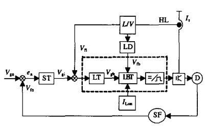
2, the design of the control systemIn some special application environments, such as elevators, lifting, traction, etc., the start, stop and operation of the drive and drag system are required to be very stable to enhance comfort and safety. Figure 1 is a typical closed-loop control system. In the figure, Vgn is the center control microcontroller given speed, Vfn is the feedback speed, and the difference between the two is generated by the speed regulator to give the given current signal Vgi. The closed loop is called speed adjustment. ring. Vgi and the current Vfi detected by the Hall current sensor HL are differenced and then enter the current regulator LT. The regulator is adjusted under the maximum current limit, and the output waveform control signal Vgb is controlled by the current rate change control circuit LBT. A PWM pulse that drives the IGBT is generated. The current change rate signal is generated by differentiating the current signal from HL through the differential circuit LD, and Vgb is adjusted in the LBT to limit the increase in the current change rate. In the control system shown in Fig. 1, the inside part of the dotted line frame is designed using UC3846. The following describes the design principles.

Figure 1 Closed loop control block diagram
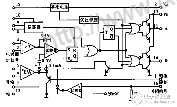
2.1, current type controller principleIn addition to the full function of the voltage type PWM controller, the current type controller also needs a current detection link. The detection point can be arbitrarily selected according to requirements, such as the switching tube current, the inductor current or the total output current sent by the HL sensor. . The following uses UC3846 as an example to illustrate its working principle. Figure 2 shows the internal structure of the chip. The difference between the figure and the voltage type control device is that a current measuring amplifier is set with a gain of 3. The E/A amplifier is an error amplifier. The output is diode-biased and biased to 0.5V and sent to the opposite end of the comparator. The current measurement signal is three times after the non-inverting terminal. The output of the current measuring amplifier is limited to 3.5 V or less by the internal circuit, and therefore, the maximum voltage value of the current measuring signal is limited to 3.5/3 = 1.2 V. The current measurement link parameters can be selected according to 1.2V. For current mode control, in order to ensure that the output current is constant and is not affected by the duty cycle d, slope compensation must be performed. The method is: superimposing a sum of a triangular waveform derived from an oscillator waveform and an inductor current waveform at the input of the current detecting amplifier (4 feet) or the output of the error amplifier (7 feet), that is, the slope compensation is completed, and the amplitude thereof should be Greater than l/2 of the slope of the current waveform.

Figure 2 Internal structure of the UC3846
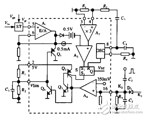
Figure 3 shows the schematic diagram of the internal and external circuit connections of the UC3846. In the figure, S is a PWM register, and there are two set terminals S1 and S2, which can make y. . Is high, blocking the PWM output. In the design, the output of A is accepted by sl. When the output current I is greater than the given value, the output of A3 is high, thus forming the trailing edge of PWM. The S2 terminal accepts control of two control signals K1, K2 formed by an external circuit. K1 is used as the circuit to turn off, and K2 is the output of the output detection current I through the differential circuit. The function is to turn off the pulse output when the current change rate exceeds a certain value. In the figure, R5C. constitutes a slope correction network to correct the output current. The working principle of the current loop and the current rate change loop are discussed separately below.

Figure 3 Part of the uc3846 internal structure and external connection diagram
Sunset Lamp,Room Lights,Led Ceiling Lights,Kitchen Ceiling Lights
Jiangmen soundrace electronics and technology co.,ltd. , https://www.soundracegroup.com
