
Synchronous buck powertrain design is one of the most commonly used converter topologies today, but choosing the right powertrain component for a medium to low voltage synchronous buck converter can be a daunting task. Designers must choose power MOSFETs from a range of seemingly infinite devices, and simple quality factor (FOM) comparisons typically do not have optimal conversion efficiency or cost. Looking at the big picture, if you try it out by conventional methods, you must use actual circuit loss and energy efficiency data for comparison, which is a cumbersome and time consuming process. It can be time consuming and laborious to specify passive components such as output filter inductors, capacitors, and buffers by manual calculations. Taking into account the challenges faced by engineers, ON Semiconductor has developed a new synchronous buck powertrain design tool.
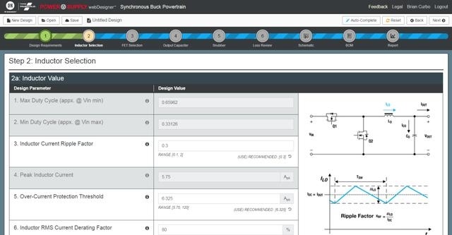
The new synchronous buck powertrain design tool provides complete powertrain system design and analysis, including power MOSFETs, output inductors, output capacitors, and optional buffering, so you can complete a solution in less time. It works like a power supply design tool, Power Supply WebDesigner, to complete a design in minutes, just enter your system requirements, click on "Auto-Complete", or use the guide design to fine-tune it in all design steps. Loss and energy efficiency analysis to schematics, bill of materials (BOM) and design reports. Have useful "information comments" without reference to application notes. Based on our FETBench for discrete component analysis, we support MOSFETs up to 250V BVDSS in single, dual symmetrical and dual stage asymmetrical (power stage) configurations. As for the ultimate flexibility, you can still use it with any controller or drive you want.
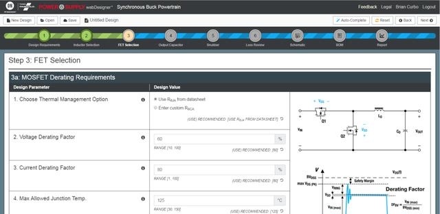
The Synchronous Buck Powertrain tool automatically searches for a comprehensive database of MOSFETs through guided device selection and recommends high-side and low-side switches to meet your system requirements. The user can select another FET from a pre-sorted list of suitable devices. The parameter data, losses and junction temperatures for the different high-side and low-side FETs can be compared simply and quickly to the right of the selected table. Complete the powertrain, recommend and select a true inductor code, and specify the output capacitors according to system requirements. Finally, an RC buffer for the switch node can also be specified.
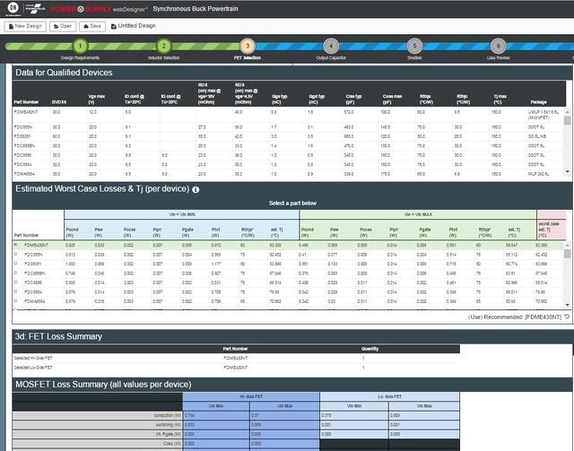
The new synchronous buck powertrain design tool has improved accuracy, adjusting your printed circuit board design through MOSFET loss calculations, including iterative Rds(on) versus temperature effects and optional custom thermal impedance. You can enter your preferred controller/driver data, such as independent high and low side gate drive voltages, source/æ±² resistance, delay time, and gate damping resistors for higher accuracy. This tool provides more detailed loss and energy efficiency analysis, such as the generation of MOSFET losses (conduction, switching, reverse recovery, etc.). The total powertrain losses can be analyzed for each component and provide loss and energy efficiency maps for a variety of input and load conditions.
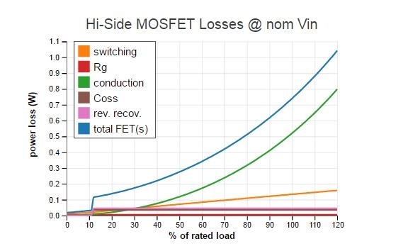
MOSFET loss details*

The development of this tool combines decades of power supply from ON Semiconductor engineers. With all of these features and flexibility built in, you'll be able to complete your powertrain solution with less time and effort.
Enclosure Junction Box,Ip44 Waterproof Terminal,Electronic Connector Box, Outdoor Cable Connectors,junction box
Guangdong Ojun Technology Co., Ltd. , https://www.ojunconnector.com