Summary
An understanding of drive installation options can help users save money, reduce downtime, and increase the safety of motion control systems.
Cost is often the deciding factor when choosing where and how to install a low-voltage inverter. However, placing costs before making key decisions about installing a drive can result in higher cost of ownership. It also increases the likelihood of unplanned downtime and creates potential safety issues.
Regardless of whether the user plans to install the drive in a new or existing facility, the following environmental and safety issues should be considered first.

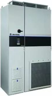
Figure 1: The performance of the drive can be optimized only if the user understands the inherent risks and benefits of the installation options. Image source: Rockwell Automation
Environmental problems of the inverter
High temperature is the biggest enemy of inverter reliability. If management is not effective, heat can build up on the junction of the power transistors of the drive. This can cause the knot to melt or melt.
Overheating can also jeopardize the intelligent power module of the frequency converter. That would affect hundreds of small discrete components and components that work together inside the drive.
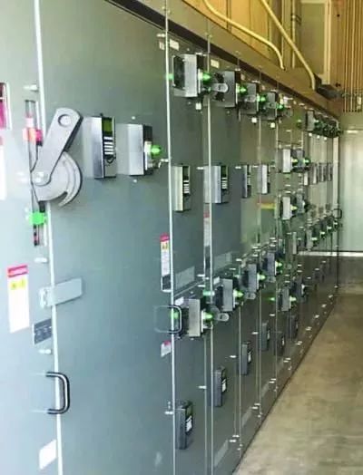
From an environmental point of view, installing a frequency converter in the Motor Control Center (MCC) is an ideal choice. UL-845: Motor Control Center requirements and test procedures address overheating management issues throughout the MCC alignment. This means that the MCC manufacturer needs to prove that the frequency converter installed in the MCC will not be damaged, or that the heat generated by the inverter will not damage other equipment in the MCC.
However, an important point to remember is that the correct thermal management and assembly equipment on the UL-845 list can only be done by the MCC manufacturer. Even panel manufacturers certified under UL-508a cannot add the frequency converter to the MCC and cannot maintain their UL-845 list. If a unit within the MCC is not in the UL-845 list, the list of entire MCC arrangements is invalid.
If a set of frequency converters is installed in an industrial control cabinet (ICP) rather than in an MCC, the end user is burdened with thermal management.
If the ICP must be sealed, an air conditioning unit is typically required to maintain the internal temperature within the design limits of the drive (or other ICP component limits). A common rule of thumb is that the frequency converter will probably release 3% of the total power flowing through it, radiating heat into its surroundings.
When venting the ICP, the total amount of air exchange at the highest outdoor temperature must be sufficient to keep the internal temperature within the design limits of the drive. Moreover, if the circulating outside air contains dust or moisture, a filter must be used to eliminate the contamination. Maintenance failures and periodic filter changes can cause components to overheat.
Another key heat-related problem for frequency converters installed in ICP is to leave enough headroom around the frequency converter for normal air flow. Each drive is designed with minimum clearance required, including top, bottom, and side to side, which are critical for cooling internal boards and components.
It is often seen that some inexperienced panel manufacturers mistakenly assume that the slotted cable duct does not become an obstacle, so it is placed too close to the frequency converter. However, it becomes an obstacle to normal air flow and does not leave enough headroom, which often leads to premature failure of the frequency converter.
Wall mounted drives are usually equipped with a fan that drives air through the outer casing of the drive for cooling. Also consider other substances that may be present in the surrounding air, including water vapor, oil, dust, chemicals, and gas. These substances may enter the frequency converter and cause damage, or cause debris to build up and reduce cooling efficiency. Preventing obstacles from obstructing air flow is equally important for wall-mounted drives.
Certain gases, such as hydrogen sulfide, should be avoided as it can erode printed circuit boards and connecting components. Moreover, it is necessary to keep the relative humidity above the minimum when using certain transmissions, because if it is too low, static electricity becomes a problem when air flows through the components. This is especially important for low voltage drives that do not use a conformal coating on their boards.
For inverters with a motor model of 400 hp or more, it is too large to be installed on the wall and can only be installed in a separate structure that can be fixed on the floor. These cabinets, called cabinet mounts, require a separate air passage to cool the heat sink.

Figure 2: Users should be aware of the inherent risks and benefits of different installation options to optimize the performance of the drive.
Proper drive safety
The safety of the arc is of particular concern when deciding how and where to install the frequency converter.
The most convincing reason for installing a frequency converter in the MCC is that its safety is consistent with the overall design of the MCC. When installing the frequency converter in the MCC, all personnel safety issues are related to the entire MCC decision making process. If the MCC is to have arc resistance, the cabinet of the frequency converter must also be resistant to arcing.
In addition to arc flash protection, there are some other personal safety issues related to MCC installation:
In a UL-845 MCC unit, the drive must be in a tested series of combinations (which should be performed by the MCC manufacturer) at a level that meets or exceeds the MCC short-circuit rating. As long as the overall MCC specification meets the site conditions, this will ensure that each unit within the MCC is certified to be connected to the system.
The human machine interface (HMI) required by the user to access the frequency converter is usually moved to the outside of the equipment unit door in the form of an MCC unless otherwise specified. This means that when the operator wants to read, adjust, program or troubleshoot the drive on his display, they do not need to open the unit door and expose it to the safety hazard in the cabinet.
If you install a drive inside an ICP, you also need to consider multiple safety issues. If the user does not require a short circuit current rating (SCCR) in the purchase instructions, some ICP manufacturers will provide a ICP with a 5kA rating in good faith. This means that the user cannot connect the ICP to a power system with a possible fault current (AFC) above 5kA. However, in fact, 5kA AFC is unlikely to be achieved in industrial applications, especially when using 480V power.
Moreover, arc flash safety and the requirement to lock and hang out usually means that the main circuit breaker of the ICP should be disconnected, and the interlocking and tagging operations should be performed before any operation inside the ICP or connection of the ICP. It is extremely difficult to manage multiple circuit breaker devices that pass through the door. In the case where part of the system is turned off and the entire system must be shut down, the ICP will be more sensible than the MCC or a separate frequency converter.
At the same time, SCCR is also critical for wall-mounted and cabinet-mounted inverters. If possible, purchase the frequency converter as a combination unit, as the main circuit breaker and overcurrent protection are integrated into the inverter package. This solves the SCCR problem as well as other electrical safety issues.
Another problem associated with large frequency converters is that they are usually heavy. For example, maintenance technicians often use tools, cranes, and even forklifts, putting inverters and workers at risk. An introduction to the chassis design uses a special truck-like design that matches the internal rails at the bottom of the drive cabinet, providing a simple and safe way to move heavy equipment components.
The accessibility, safety, maintainability, and suitability of the drive installation can have long-term effects that are not immediately apparent during the design and planning phases. By understanding the inherent risks and benefits of different installation options, users can optimize their performance throughout the life of the drive, while also reducing downtime and security risks.
Motion control sensor is an original part that converts the change of non-electricity (such as speed, pressure) into electric quantity. According to the converted non-electricity, it can be divided into pressure sensor, speed sensor, temperature sensor, etc. It is a measurement, control instrument and Parts and accessories of equipment.
Remote Control Motion Sensor,Photocell And Motion Sensor,Homeseer Motion Sensor,Lutron Motion Sensor Caseta
Changchun Guangxing Sensing Technology Co.LTD , https://www.gx-encoder.com
