In switching power supplies, the general practice is to connect the AC input power supply to the rectifier and connect a large energy storage or filter capacitor through a low impedance noise filter. In order to avoid large inrush currents when power is first applied, a surge control circuit is usually provided. In high-power systems, the surge suppression is often composed of a series resistor. After the input capacitor is fully charged, the series resistor is short-circuited with a triac, SRC or relay.
In order to allow the input capacitor to be fully charged during startup, it is necessary to delay the startup of the power converter so that the power converter draws current from the input capacitor after the input capacitor is fully charged. If the capacitor is not fully charged, a current surge will occur when the surge control thyristor or triac thyristor bypasses the surge suppression series resistor. In addition, if the converter is allowed to start at the maximum pulse width, there will be large current surges into the output capacitor and inductance, causing the output voltage to overshoot, which is caused by the large current of the output inductor and possibly the saturation effect of the main transformer. .
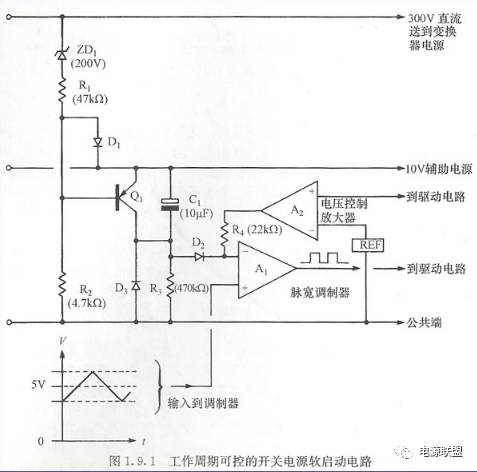
In order to solve these startup problems, the control circuit is usually used to provide startup delay and soft start procedures. This will cause the initial turn-on delay of the converter and allow the input capacitor to fully charge. After the delay, the soft-start control circuit must start the converter from zero and slowly increase the output voltage. In this way, the transformer and the output inductor can be put into normal operation to prevent the "double magnetic flux effect" in the push-pull circuit. Since the formation of the output voltage is relatively slow, the current surge of the secondary side inductance is reduced, and the tendency of the output voltage overshoot is weakened. The soft start circuit of the soft start circuit is shown in Figure 1.9.1. The operation is as follows.
When the switching power supply is connected for the first time, C1 will discharge. The gradually increasing voltage on the 10V switching power supply line will make the inverting input of amplifier A1 positive, prohibiting the output of the pulse width modulator. Transistor Q1 will conduct through R2, maintaining the C1 discharge state until the voltage developed across the 300V DC line to the converter circuit exceeds 200V.
At this point ZD1 will start to turn on and Q1 will turn off. C1 will charge through R3, pulling the inverting input voltage of A1 to zero and allowing the output of the pulse width modulator to provide a pulse of increasing width to the drive circuit until the desired output voltage is formed. When the correct output voltage is established, amplifier A2 controls the voltage at the inverting input of amplifier A1. C1 will continue to charge through R3, reverse biasing diode D2 and leaving C1 no longer affected by the modulator. When the switching power supply is turned off, C1 will quickly discharge through D3, resetting C1 for the next startup action. When the input voltage is high, D1 prevents Q1 from being reverse biased by the voltage greater than the forward diode voltage drop. .

1.9.1 controllable duty cycle of the switching power supply of FIG soft start circuit only provides this on-delay circuit and a soft start, and provides low inhibitory effect, to prevent the transformer started before the power supply is fully established. This basic principle may have many changes. Figure 1.9.2 shows a soft-start system applied to the transistor startup circuit in Figure 1.8.2. In this example, the ZD2 input goes high until the auxiliary capacitor C3 is charged and Q1 is turned off, and the soft start begins. Therefore, in this circuit, the switching power supply voltage and the auxiliary power supply voltage must be correctly established before the soft start can be started. This will ensure that the converter starts up under the correct control conditions.
The product is used for cutting reinforced concrete, granite quarry and marble
sawing wire, sawing wire rope, wire rope for cutting, wire rope for marble cutting, wire rope for stone cutting
ROYAL RANGE INTERNATIONAL TRADING CO., LTD , https://www.royalrangelgs.com
