This article details the difference between the analog and digital circuits in the PCB. For everyone to understand clearly... I used ORCAD to draw two circuits, one is an ordinary triode analog amplifier circuit, and the other is a digital circuit oscillator... well no nonsense... above.. .
The following is a circuit diagram of two circuits when grounding at one point...
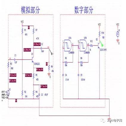
In fact, there is no need to draw a little grounding in the schematic diagram like this... It is just for everyone to see more clearly.... You can see it, the left side is the ordinary amplification circuit... The right side is an oscillator.. Because the current in the digital circuit part is too small during the simulation, it is connected to the first-level transistor...
Below are the waveforms of the two circuits...
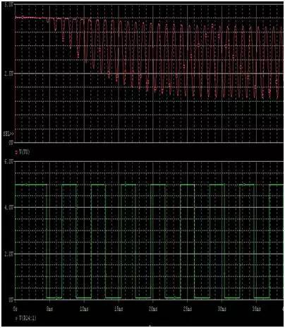
Everyone can see... these two waveforms... are very good..., no distortion....
The red is the waveform when the triode amplifier is amplified... Green is the oscillator waveform... Someone may want to ask the red why the previous waveform does not work... that is because the actual power supply is simulated in ORCAD... There is electricity... there is a time... so the previous waveform is very small...
Everyone can see that there is a little grounding, and both circuits have no effect.... It is normal to work with each other...
The following is not a circuit diagram when grounding....
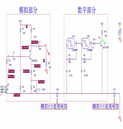
I use two resistors here to replace the resistance of the trace on the PCB... I think someone will definitely say that this is not a bang, how can the resistance on the PCB be so large. 50 ohms...haha. Here I am For everyone to see more intuitive, so use so big... In fact, it won't be so big...but compared to high frequency circuits, sometimes the impedance of the wire is much smaller than the inductive resistance!!! It is possible to generate such a large resistance. Here is the digital circuit connected behind
The following is the simulation waveform of the two circuits.... Will it be the same as before?
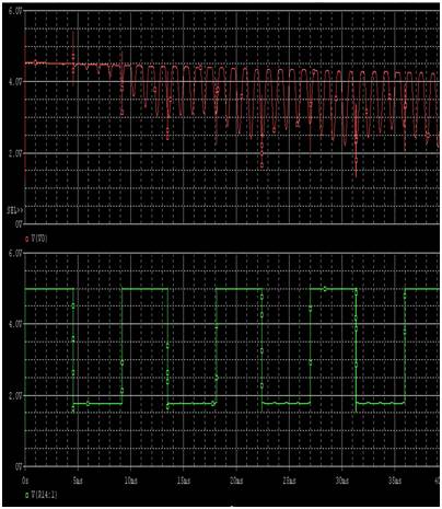
You can see that the waveform amplification of the analog circuit is disturbed by the unsatisfactory...
Send a simulated waveform separately...
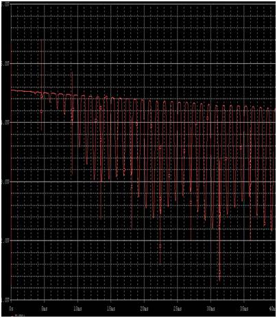
This distortion is terrible....
The following number is issued... Because the number of cloth is close to the power supply... the interference is not very serious...
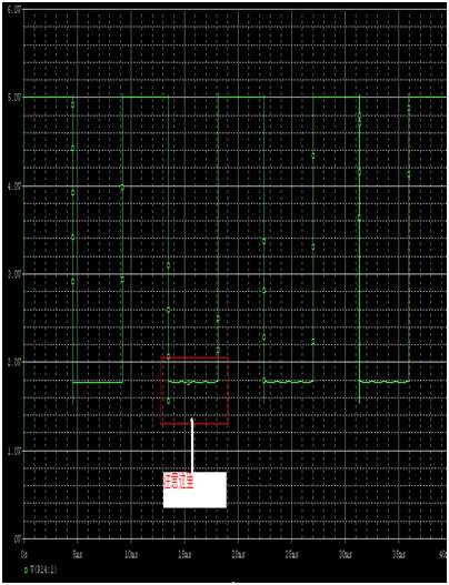
Everyone can see that the digital circuit is still being disturbed.....
Send another enlarged picture to see everyone...
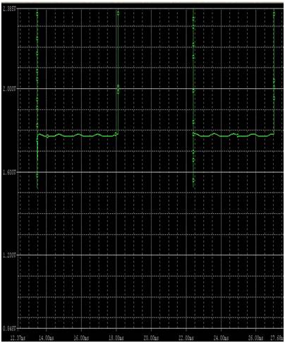
Everyone can see... it’s been disturbed by the simulation...
Medium Rate Nicd Battery KPM Series
Established in 1956, during the China first five-year-plan, Henan Xintaihang Power Source Co., Ltd. (Factory No.755) was the first R&D and manufacturing enterprise in China in the field of alkaline storage batteries and modular power system and it was also the military factory which owned the most varieties rechargeable batteries in domestic. Taihang was located in national Chemistry and Physicals Power Source Industrial Park, Xinxiang City, Henan, China.
Medium Dishcharge Rate Nickel Cadmium Battery, KPM10~KPM1000, 0.5C ≤Max. discharge current <3.5C
The nickel–cadmium battery (NiCd battery or NiCad battery) is a type of rechargeable battery using nickel oxide hydroxide and metallic cadmium as electrodes. The abbreviation NiCd is derived from the chemical symbols of nickel (Ni) and cadmium (Cd).
Ni Cd Rechargeable Battery,Kpm500Ah Battery,Medium Discharge Rate Nickel Battery,Nickel Cadmium Battery For Ups
Henan Xintaihang Power Source Co.,Ltd , https://www.taihangbattery.com
