I. Brief description:
The peel strength tester can be selected for testing the adhesive strength of the transparent adhesive tape. The industry is also called the peel strength tester. The computer system peel strength testing machine is a test instrument designed and developed for the adhesive tape and adhesive industry and used for peeling strength testing of various adhesive products in different ways. Different types of jigs can be used for the peel test of 180 ÌŠ, 90 ÌŠ, T-shaped and floating roll method (for high-strength adhesives) and the tensile shear strength and splitting strength of the adhesive.
two,
Preparation tool
1.
The peel strength tester (with a clamp) can be electronic or computer type.
2.
Transparent tape.
3.
Rulers, measuring sample size may need to be used.
4.
Manual rolling roller
5.
Many pieces of clean and scratch-free steel plate.
6.
Scissors, used to cut adhesive tape.
7.
Pen and paper, record data.
two,
Method of operation (standard use order)
↓A.Connect and turn on the power of the host and printer to prepare the test piece;
↓B. Adjust the upper and lower clamp distances and set the upper and lower limit safety switch setting rings to the appropriate position (first use);
↓C. Press the test button (Test) of the PT-2000 display to start the test;
↓D. The test is over and the results are recorded;
↓ E. Return the fixture to the origin;
↓F. Conduct a second test...
1.
Plug the power cord into the power input socket on the back of the instrument base and connect the single-phase AC200240V/50Hz power source. The printer is connected to a 220V power supply. (LOAD1 is the first group of load cell interfaces, LOAD2 is the second group of load cell interfaces, press the power switch);
2.
Install the upper and lower clamps and adjust the setting ring of the upper and lower limit safety switches. Press the Up key or the Down key to test whether the position of the automatic return of the machine and the position of the upper and lower clamps are appropriate to prevent the clamp from rising or Crashing the instrument when falling;
Note: Tighten the upper and lower limit setting rings after setting.
3.
The test piece is clamped on the fixture, and no tensile force may occur during the clamping process of the test piece, so as not to affect the test result;
4.
Enter the parameters (number, area, gauge length, etc.) of the measured object and set the test parameters (test method, test speed, holding force, percentage of downtime, point and unit, etc.);
5.
Press the Test button to enter the test directly;
6.
The test piece is broken or destroyed automatically, the value and curve of the display are recorded and the printout is selected;
7.
Return the clamp to the second test.
three
,Precautions
1.
Set the upper and lower limit safety switch setting rings. The upper and lower limit safety distance adjustments are different depending on the fixture;
2.
When operating the machine, the operator should not leave, pay attention to the upper and lower clamps can not collide;
3. The configuration and load of each test machine are different.
Do not overload it;
4.
This product is a precision instrument and should not be used in places with excessive dust or excessive humidity;
5.
When the operator replaces, please hand over the operation method and precautions;
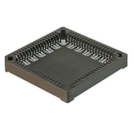
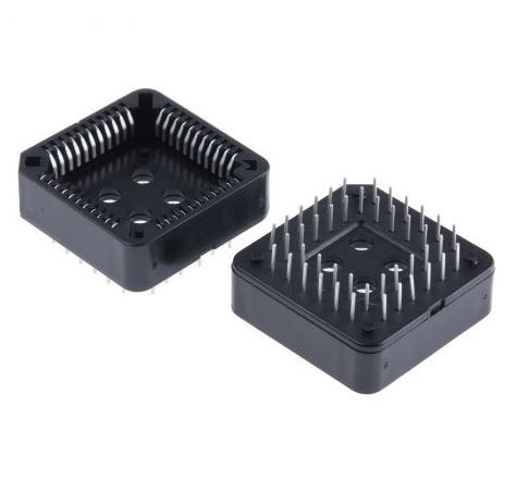
Antenk PLCC connectors Series Sockets are low profile, thin wall sockets designed to convert plastic leaded chips to a thru-hole PCB format on a .100" centerline grid.Antenk's superior precision stamped contact design provides consistent, high retention contacts for all size chips.

PLCC Connectors -PLCCSockets
A PLCC socket is a component that connects a chip carrier to an electronic circuit via surface-mounting or through-hole technology.
Plastic leaded chip carriers (PLCCs) are used in surface-mount technology where electronic circuits are produced, and components need to be mounted or placed directly onto a printed circuit board (PCB). The chip carrier is placed in a PLCC socket, which is either surface-mounted or features through-hole technology. A specialised tool called a PLCC extractor is needed to remove the chip carrier from the PLCC socket.
What are PLCC sockets used for?
PLCC sockets are used in surface-mount device (SMD) and surface-mount technology (SMT) applications. PLCC sockets made of heavy gauge copper alloy are compatible in high shock / high vibration applications. PLCC sockets made of rolled-leaf copper are useful in low-cost computer applications.
Types of PLCC sockets
The two primary categories of PLCC sockets are:
Surface-mount PLCC sockets, which are used in devices sensitive to heat from the reflow process. These allow for component replacement without redesigning or reworking the entire PCB.

Through-hole technology PLCC sockets are necessary when a device requires stand-alone programming with flash drives or memory devices. These are also beneficial for prototyping activities where wire wrapping is required.

Plcc Socket,Plcc Connector,Plcc Socket Connector,Smd Plcc Connector,PLCC Connector DIP,PLCC Connector SMT
ShenZhen Antenk Electronics Co,Ltd , https://www.antenkcon.com
