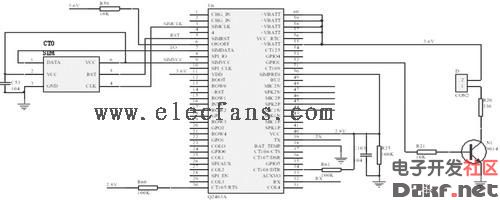
Mobile phone module and SIM card peripheral circuit diagram
Q2403A GSM/GPRS module supports dual-band EGSM/GPRS 900MHz/1800MHz mode, supports AT commands, and has short message function. The Q2403A module has a 60-pin universal interface that is easy to integrate into the application; 3V SIM card interface with SIM card acknowledgment, power, clock, reset and I/O, including SIMVCC, SIMRST, SIMDATA, SIMCLK and SIMPRES. In addition, the module provides a 6-wire serial communication interface that complies with the V24 protocol, including TX, RX, RTS, CTS, DTR, and DSR. It also provides DCD and RI signal interfaces, power-on signals PowerON/OFF, and reset signal RST. The module requires two power supplies for normal operation. VBATT is supplied to the RF section with a voltage range of 3.3V to 4.5V and a maximum power of 2 W. VDD is supplied to the baseband section with a voltage range of 3.1V to 4.5V. The maximum power is 0.5W. Figure 4 shows the peripheral circuit design of the mobile phone module and SIM card.

Shenzhen Hengstar Technology Co., Ltd. , https://www.angeltondal.com
