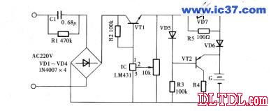
The constant current and constant voltage pulse charger introduced in this example is suitable for charging various 5th rechargeable batteries, which is convenient to use and easy to manufacture.
working principle
The circuit of the constant current constant voltage pulse charger is divided into three parts; that is, the capacitor step-down rectification part, the pulse charging part and the discharge part

220V AC power is stepped down by capacitor C1, VD1~VD4 bridge rectification without filter capacitor, the output is
Pulsed direct current. The base of the transistor VTl is connected with a high-precision three-terminal adjustable integrated constant current source IC (LM431), which can be adjusted.
The control pole of the IC regulates the base potential of VT1. VTl is connected to the emitter output, and the emitter potential changes with the base voltage.
This makes it possible to adjust the level of the pulse voltage by adjusting the RP. The discharge part is completed by the triode VT2, the VT2 base
The voltage is divided by diode VD5 and resistor R3. According to the characteristics of VT2, during the positive pulse, VT2 intercept
only. After the positive pulse, the charge is suspended and VT2 is turned on to discharge the battery. How much discharge is affected by the VT2 emitter resistance
Limitation of R4. VD7 is the charging indicator, and VD6 prevents the battery from discharging to VD5 when the battery is stopped. This charger is actually a
The constant current constant voltage pulse charger does not damage the battery even if it is charged for a long time. According to the charging voltage
Find, adjust the RP to the required voltage.
Component selection
Ic uses a three-terminal adjustable integrated constant current source LM431.
VTl selects 9013 or 3DG12, 3DK4 type silicon NPN medium power transistor, requires current amplification factor β>100;
VT2 selects 9012 or 3CG12 type silicon PNP medium power transistor, which requires current amplification factor β>1000
VD1~VD6 selects 1N4007 type silicon rectifier diode; VD7 selects Φ3mm red LED.
R1 is best to use RJ-1W metal film resistors; the rest of the resistors are RTX-1/8W carbon film resistors. RP
Use WSW type organic solid trimming resistor.
C1 requires the use of CBB-400V polypropylene capacitors.
Production and debugging
Install all electronic components on a self-made printed circuit board and load them into plastic or wooden of appropriate size
Inside the box, fix the LEDs VD7 and RP on the surface of the box, and install the No. 5 dry battery clip in the box, and put it in charge.
Battery. Since the capacitor is stepped down, the circuit is connected to the mains, and safety must be taken into account during use. Generally good first
After being charged, turn on the charging power. After charging, turn off the power and then take the battery to prevent the risk of electric shock.
CCTV Microphone,Microphone For Security Camera,Cctv Audio Microphone,CCTV Audio Picker
Chinasky Electronics Co., Ltd. , https://www.chinacctvproducts.com
