description:
The universal semiconductor measuring circuit is matched with the multimeter and has nothing to do with the computer. If the ammeter and the voltmeter are integrated, it is necessary to pay attention to the independent power supply of the meter. Because the measured Ib and Vgs voltages are all floating.
Another worst point is that the hfe reading is inconvenient because hfe=Ic/Ib, Ic is fixed, the ammeter measures Ib, and Ib is inversely proportional to Hfe, which means that hfe is required. Can't read Hfe directly, it will be inconvenient to use.
Need 3 sets of switches:
- S1~S4 is a dual 4-select switch for selecting the measurement current. The measured Ic is 1A, 50mA, 2mA, 10uA corresponding to high power tube, medium power tube, small power tube, FET pinch-off voltage measurement.
- Sw1 is the measurement base current / Vgs, Vbe selector switch
- Sw2 is a measurement type switch
The circuit description is as follows:
The rectifier bridge and the FET tube form a bidirectional constant current circuit, so the voltage across P1~P4 is constant.
The op amp and the measured tube form a closed-loop constant current circuit, so the voltage across R2~R5 is also constant, that is, the collector collector Ic/drain current Id is also constant.
The ammeter is connected in series between the op amp and the base of the tube under test. Therefore, the base current is inversely proportional to the hfe of the tube under test. Similarly, the voltmeter is connected in parallel between the BE/GS of the tube under test, so this voltage is the collector/ Corresponding Vbe/Vgs voltage under drain current
No matter what PNP or NPN or MOS type tube you insert, the voltage of P1~P4 is constant due to the bidirectional constant current source, so the current of R2~R5 is also constant, regardless of the type of tube being tested, so this circuit The Hfe, Vgs, and Vbe values ​​of the P and N tubes can be quantitatively measured.
The complementary MOS tube and the 4 diodes on the right side mainly ensure the normal input voltage of the op amp. In the form of MOS tube and diode, the emitter of the tube under test is at least 5V higher than the ground (Vcc), so that the JFET tube is not measured. problem.
In theory, the result of this circuit measurement is far more accurate than other circuits, and no need for precision components, only a multimeter calibration can be used, the multimeter can not be shared with the measurement power supply.
The correction is simple:
Insert a normal power MOS tube, and connect the ammeter at the TP point, select the corresponding current range, and adjust the corresponding P1~P4 to make the current of the ammeter correct.

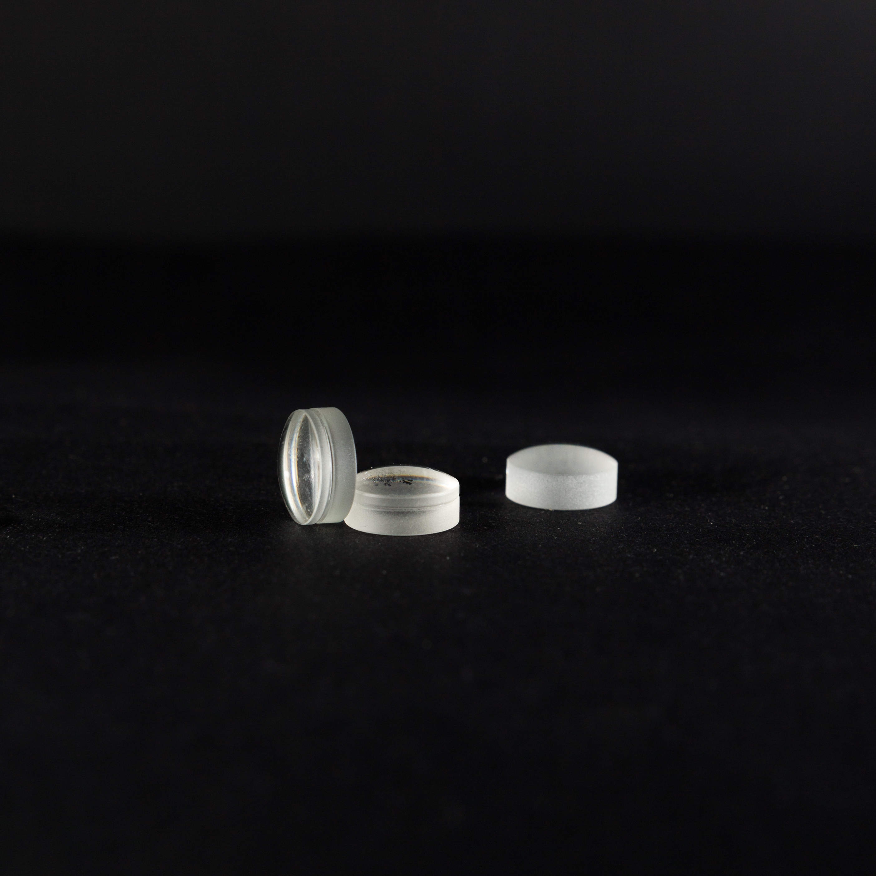
Glued lens, also known as achromatic lens, is formed by gluing two single lenses. The performance of multi-color (white light) imaging is much higher than that of single lens. Achromatic lenses are glued together by two lenses with different materials to correct the dispersion of the glass. The achromatic lens has been widely used in multi-color lighting and imaging, and the cost-effectiveness is improved.

Achromatic Lens,Achromatic Lens Optical,Positive Achromatic Lens,Negetive Achromatic Lens
Hanzhong Hengpu Photoelectric Technology Co.,Ltd , https://www.hplenses.com
